Baitong Kexin
Contact

Vehicle Diagnosis

High-Voltage Fault Diagnosis Training

Move from fault symptoms to circuit reasoning, permitted measurements and documented conclusions. Use vehicle-matched access points and instructor-managed faults for repeatable practical work.

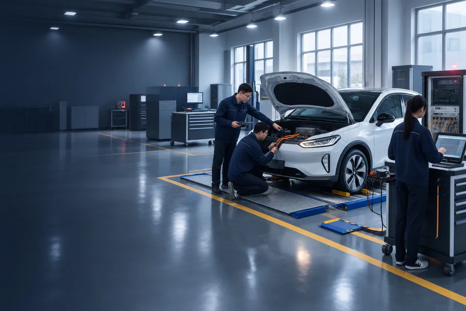
Learners working with vehicle diagnostic equipment around an open engine bay
Illustrative EV diagnosis scene showing a vehicle, diagnostic equipment and learners working around an open engine bay.

The Training Route

Trace Symptoms Through Measurements to a Verified Diagnosis.

Develop a diagnostic method that connects the reported symptom, vehicle circuit information, permitted measurements and verification after restoration.

  1. Plan from the Symptom

    Learner Practice

    Review the instructor-selected case, compatible scan-tool data and actual vehicle diagram to choose the next diagnostic measurements.

    Evidence of Learning

    Produce a circuit-based diagnostic plan with a reason for each proposed check.

  2. Measure and Explain

    Learner Practice

    Take permitted readings through the matched adapter and designated measurement points, recording the conditions and decision points.

    Evidence of Learning

    Support the fault conclusion with traceable measurements and circuit reasoning.

  3. Restore and Verify

    Learner Practice

    Follow the approved restoration procedure and check the vehicle response against the completed diagnostic record.

    Evidence of Learning

    Document the evidence that the selected fault has been resolved.

The Equipment Combination

Connect the Tasks with the Right Equipment.

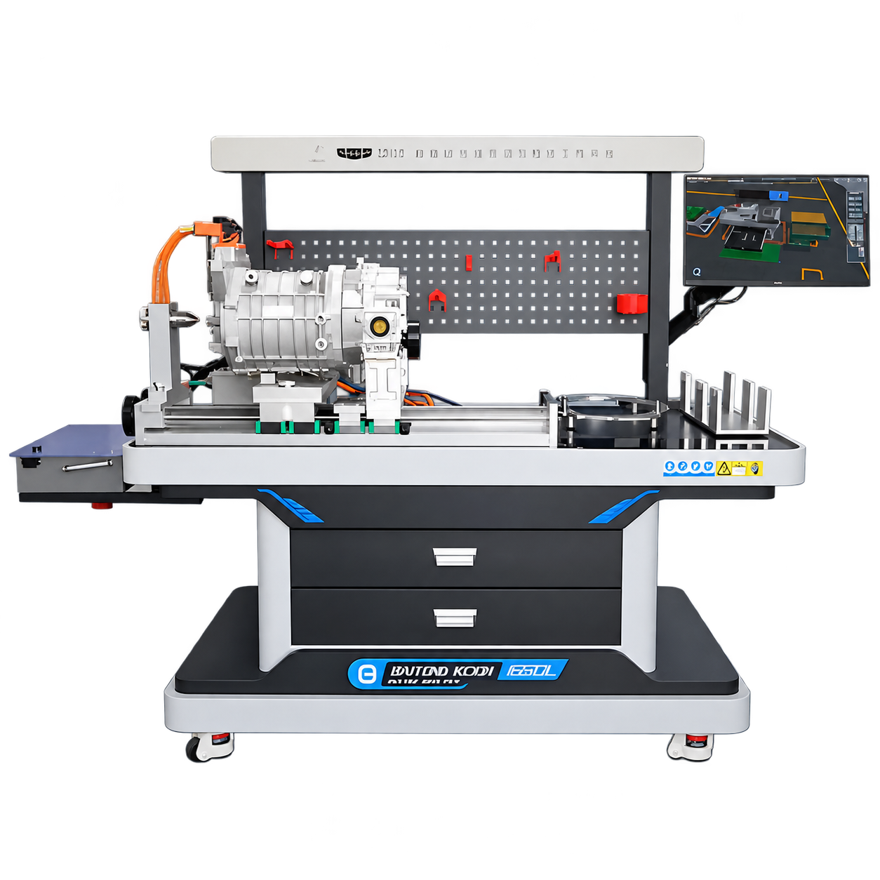
T136 works with a specified compatible EV through matched adapter harnesses. Select the circuits, instruments and validated fault exercises for that vehicle, with its diagnostic evidence and restoration procedure defined alongside the workstation.

Technical Configuration and Operating Limits
ItemTeaching Configuration
WorkstationBT-NEV2-T136, used with a specified compatible electric training vehicle; cabinet, computer/display, measurement panel, fault boards, adapters and storage.
Fault-board capacityAt least 256 paths by design. This is not a promise of 256 validated faults on every vehicle.
Teaching coverageElectric drive, battery and vehicle control. Confirm each ECU, circuit, measurement point and permitted fault in the project schedule.
Connection methodMatched adapter harnesses provide access without cutting the original harness. Installation and operation still require the approved vehicle-specific procedure.
Display and supplyReference display ≥55 inches; computer and display supply 220 V AC. Confirm the final hardware schedule and vehicle supply arrangements.
Related G6 teaching systemsCurrent G6 motor-platform record: ≥80 test terminals and 20 fault cases; current low-voltage platform: ≥120 test terminals. Confirm each platform’s independent circuit and fault list.
Diagnostic evidenceApproved instrument readings, compatible scan-tool data, circuit reasoning, fault conclusion and verification of restoration.
Separate scope itemsState whether the training vehicle, diagnostic instruments, software and manuals are supplied or school-provided.

From Equipment to Teaching

Build a Repeatable Teaching Routine.

Ask groups to move from the reported symptom to a justified measurement plan, then record the diagnosis, restoration and verification as one practical exercise.

Circuit Investigation

Have learners choose permitted point-by-point measurements from the actual vehicle diagram and explain why each check follows from the symptom. Use diagnostic codes as one source of evidence within the wider circuit-based investigation.

Controlled Fault Practice

Use the matched adapters and instructor-approved fault controls for each exercise. Teach isolation, connection and restoration as part of the vehicle-specific sequence, explaining that access without cutting the harness still requires the approved electrical precautions.

Varied Diagnostic Reasoning

Rotate the validated fault library and vary the evidence learners must provide. New cases enter the course only after circuit compatibility and permitted combinations are checked; spare board paths do not automatically create additional teaching exercises.

Traceable Diagnostic Records

Use a common measurement sheet to capture readings, conditions and diagnostic decisions. Learners build a traceable report, while any compatible simulation record supports virtual practice and remains separate from the instructor’s assessment of physical measurements and handling.

Full Instructor Notes and Scope to Confirm

Build a Traceable Diagnostic Method

Start with the reported symptom and the actual vehicle circuit information. Ask learners to explain their measurement plan, record permitted readings and connect the results to a fault conclusion.

Use the matched adapters and validated exercise list for physical practice. Virtual preparation can support the task sequence; the completed diagnostic record should include restoration and verification on the specified vehicle.

Confirm These Requirements Separately

  • A combustion-engine-only diagnostic fleet without a separately specified system
  • ECU flashing, tuning or immobilizer training
  • OEM dealership scan-tool certification assumed as part of the workstation

DTC Definitions Replace Circuit Reasoning

What to Watch For
A learner can name the code but cannot choose the next measurement or explain the relevant circuit.
Possible Cause
The exercise ends at the scan-tool screen.
Teaching Response
Require a diagnostic plan, permitted point-by-point readings and an explanation linked to the actual vehicle diagram. Treat code reading as one source of evidence.

Improvised Faults Create Real Vehicle Problems

What to Watch For
Repeated connector manipulation or an unapproved fault produces unexpected warnings, damage or electrical exposure.
Possible Cause
Faults are created directly on vehicle wiring without a validated teaching procedure.
Teaching Response
Use the matched adapters and approved instructor fault controls. Follow the vehicle and equipment isolation, connection and restoration procedures; a non-cutting harness connection does not eliminate operating risk.

Students Recognize Only Familiar Cases

What to Watch For
Known exercises are solved quickly, while an unfamiliar symptom stops the diagnostic process.
Possible Cause
The class repeats a small set without developing a transferable method.
Teaching Response
Rotate the validated fault library, vary the required evidence and assess reasoning. Add cases only after checking circuit compatibility and permitted combinations; unused board paths are not ready-made exercises.

The Diagnostic Process Is Not Recorded

What to Watch For
The final answer is correct but the instructor cannot tell whether the measurements supported it.
Possible Cause
The task lacks a record of readings, conditions and decision points.
Teaching Response
Use a common measurement sheet and require a traceable diagnostic report. Compatible simulation can record virtual task performance, while physical observations and measurements are assessed separately.

Project Experience & References

Diagnostic Standards and Vehicle Task Files

Use the specified vehicle’s competition files, applicable diagnostic assessment tasks and the cited battery-maintenance occupational standard to define the teaching evidence.

Vehicle Diagnosis and Custom Software References

The product range includes the T136 workstation and separate Geometry G6 motor and low-voltage teaching platforms. These use distinct configurations and must be specified individually.

For Guangdong Mechanical & Electrical Polytechnic, the company developed a Corolla ZRE151/152/153 comprehensive diagnosis simulation with 19 open-circuit faults. That software project demonstrates custom fault logic; it is not a claim that the Corolla uses the EV workstation’s hardware.

Documents to Review for Your Project

Review a Demonstration Against the Delivered Fault List

Request the current T136 specification, vehicle and ECU schedule, adapter list, validated fault library and demonstration session. Check how the approved exercise is selected, measured, recorded and restored.

The company’s seven-year national NEV competition supply record is supporting experience. Equipment designation should still be verified against the named event’s published equipment list and technical-file revision.

Reference Documents and Project Basis

  • Current national vocational NEV maintenance competition technical files for the specified vehicle and connection platform.
  • The national occupational standard for Battery and Battery System Maintenance Technician; Baitong Kexin is a participating drafting unit.
  • Applicable diagnostic task rubrics for the 1+X New Energy Vehicle Assembly and Testing certificate.

Application FAQs

Plan Your Training Project.

Does the 256-path board provide 256 vehicle faults?

Not automatically. The board’s path capacity is a hardware design specification. The delivered vehicle, supported circuits and validated teaching cases must be listed separately, including permitted fault combinations.

Is the platform a self-contained vehicle simulator?

No. T136 requires a specified compatible electric training vehicle. The quotation must identify the supplied or school-provided vehicle, adapters, instruments and software.

Can students practice without cutting the original harness?

The matched adapters provide designated circuit access without cutting it. Connection, fault selection, measurement and restoration must still follow the approved procedure under qualified supervision.