Baitong Kexin
Contact

Charging Systems

Charging Infrastructure Technician Training

Teach AC charging equipment assembly, pilot-signal diagnosis and protection testing in one structured program. Match the source, load and teaching charger to the approved operating range.

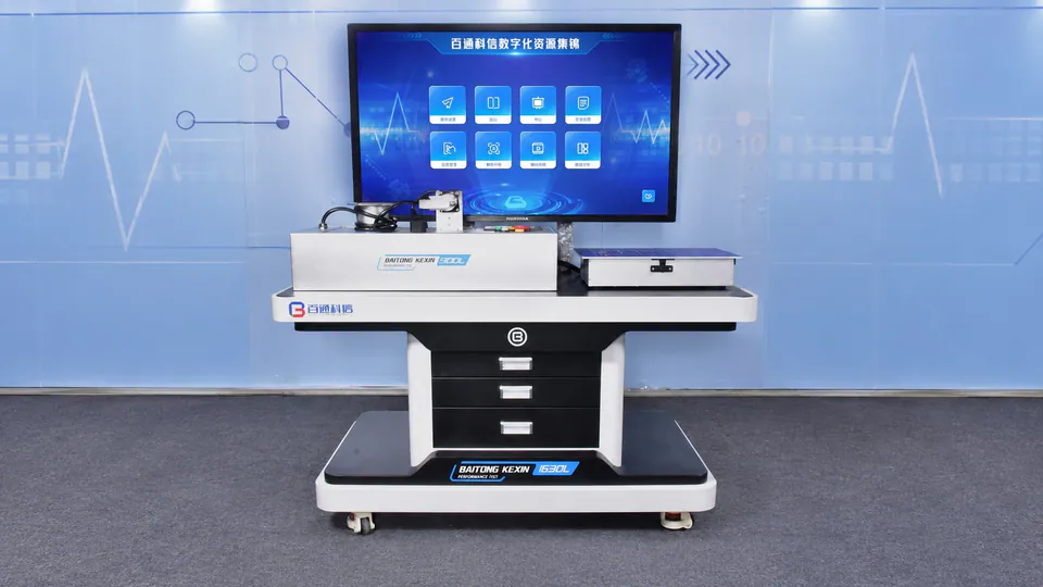
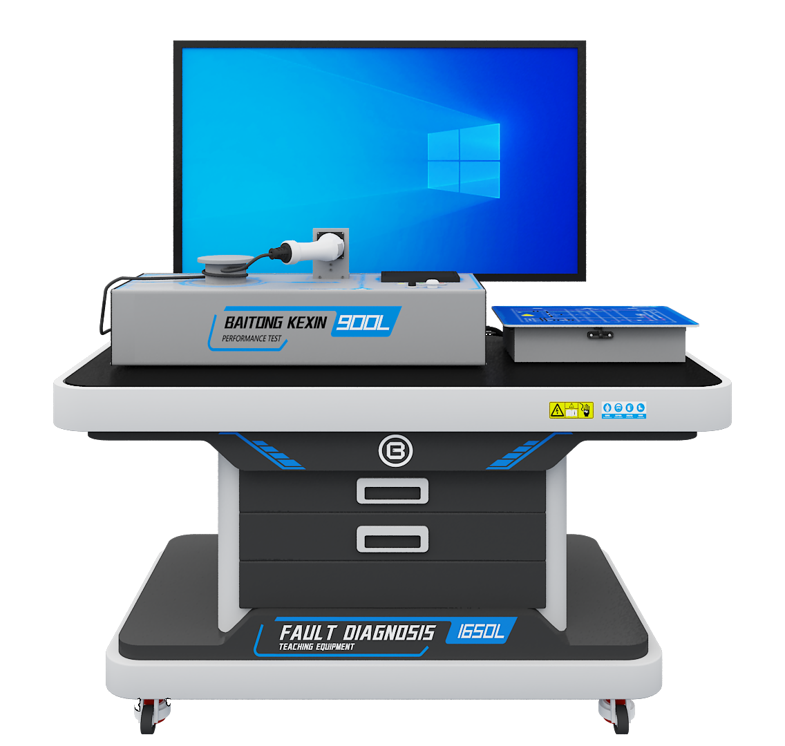
AC charging assembly and testing platform with a charging connector and teaching controls
One AC charging teaching station with a charging connector, teaching display and circuit controls.

The Training Route

Assemble AC Charging Circuits and Check Their Response.

Build component knowledge through AC EVSE assembly, then connect pilot-state measurements with charging operation and protection behavior.

  1. Assemble and Inspect AC EVSE

    Learner Practice

    Identify the charging-control, cable, connector and protection components, then perform the permitted assembly and wiring checks.

    Evidence of Learning

    Document component condition and circuit inspection before guided commissioning.

  2. Diagnose Pilot States

    Learner Practice

    Use the approved interface simulator and circuit information to compare CC/CP state changes with the charging-control sequence.

    Evidence of Learning

    Explain a charging-start problem using recorded signal and circuit evidence.

  3. Verify Protection Response

    Learner Practice

    Complete the specified earth and insulation checks and observe permitted protection-response exercises on the matched test setup.

    Evidence of Learning

    Compare the measured response with the teaching unit’s documented operating criteria.

The Equipment Combination

Connect the Tasks with the Right Equipment.

T040 supports AC charging component assembly and guided circuit checks; T083 adds programmable source, load and interface-simulation functions for the selected exercises. The teaching charger and complete setup determine the permitted operating range.

Technical Configuration and Operating Limits
ItemTeaching Configuration
Teaching charging unitT040 and T083 reference unit: ≤1.5 kW and ≤7 A; control-board input 12 V DC. T040 unit dimensions 900 × 360 × 200 mm, excluding the full workstation.
Assembly componentsControl box, charging cable and connector, residual-current protection, surge protection, energy meter, contactor and emergency stop.
Programmable source, T0830.1–300 V AC, 0.1 V adjustment accuracy; frequency 45–120 Hz. Use only the voltage and frequency allowed by the approved exercise.
Programmable load, T083Load subsystem: 0–230 V AC; adjustable 0.1–40 A with 0.1 A adjustment accuracy. Teaching charger limits remain ≤7 A.
Interface simulationR2 and R3 each adjustable from 100 Ω to 32 kΩ, with 1 Ω adjustment accuracy; confirm the supported connector and pilot protocol.
Protection thresholdsUse the ordered unit’s documented voltage, current and protection settings. Confirm the permitted demonstration procedure for the current ≤7 A teaching charger.
Practical assessmentComponent inspection, permitted circuit measurements, earth/insulation checks, documented pilot-state response and instructor-authorized commissioning.

From Equipment to Teaching

Build a Repeatable Teaching Routine.

Build lessons around component inspection, charging-state diagnosis and measured protection response, using the supplied interface and supervised procedures for each stage.

Supervised Protection Diagnosis

Use a protection trip as a supervised diagnostic exercise: stop the test, isolate as required and inspect the system. The designated interface and permitted procedure help learners distinguish the selected fault from an actual wiring or insulation problem.

Traceable Charging States

Use the approved R2/R3 simulator and circuit information to follow the expected charging sequence. Learners compare permitted state changes with recorded responses and explain their findings without modifying live power wiring.

Verified Earthing

Build protective-conductor continuity and earthing measurements into the practical record, using the specified instruments and local procedure. Learners verify electrical protection through measurements; the laboratory protective earth remains connected throughout teaching fault exercises.

Measured Protection Response

Use instructor-approved source and interface settings within the complete setup’s limits. Learners record disconnection and recovery behavior, then compare the results with the actual teaching unit’s manual rather than adopting thresholds from a different charger model.

Full Instructor Notes and Scope to Confirm

Follow the AC Charging Teaching Sequence

Organize the course around component assembly, pilot-signal diagnosis and permitted protection tests. Give learners access to the teaching points needed to inspect the circuit and explain its response.

Use charging simulation for preparation and procedure rehearsal, then assess physical inspection and measured behavior at the station. Match the charging protocol and exercises to the supplied hardware version.

Confirm These Requirements Separately

  • Commercial DC fast-charger production or grid-connection certification
  • Charge-point operator network software training assumed as part of the hardware
  • An overseas interface or standard assumed compatible without project-specific confirmation

Repeated Residual-Current Trips

What to Watch For
The protection device trips during an exercise and learners repeatedly reset it without identifying the cause.
Possible Cause
An insulation or wiring problem, component condition or leakage behavior has not been investigated under the approved procedure.
Teaching Response
Stop the exercise, isolate as required and inspect the system under qualified supervision. Use the designated teaching interface and permitted test procedure to distinguish the selected fault from a real installation problem.

Charging Does Not Start

What to Watch For
The charging sequence fails to begin even though the main assemblies appear functional.
Possible Cause
A pilot or connection-confirmation state is incompatible with the selected charging protocol, or the relevant teaching circuit is open.
Teaching Response
Use the approved R2/R3 simulator and circuit information to compare permitted state changes with the expected sequence. Record the measured response without modifying live power wiring.

Earthing Is Assumed Rather than Verified

What to Watch For
Visual inspection appears satisfactory but the recorded electrical safety checks do not meet the applicable criteria.
Possible Cause
Protective-conductor continuity and earthing measurements were omitted or confused with a visual cable check.
Teaching Response
Include the required measurements and acceptance records in the lesson. Use the specified instruments and local procedure; never remove the laboratory protective earth to create a teaching fault.

Protection Behavior Is Learned Only as a Number

What to Watch For
Students can repeat a threshold but cannot explain the measured disconnection and recovery behavior.
Possible Cause
The lesson lacks a documented, equipment-compatible protection-response exercise.
Teaching Response
Use instructor-approved source and interface settings within the complete test setup’s limits. Compare measured response with the actual unit’s manual and record the conditions; do not transfer thresholds from another charger model.

Project Experience & References

Charging Standards and Teaching Task Files

Match the charging tasks to the supplied interface and control requirements, the named competition files and the destination’s applicable framework.

Hardware Tasks Supported by Registered Software

T040 assembly and T083 performance stations are part of the current product range. Joint development with Jilin Communications Polytechnic produced AC Charging Pile Teaching System V1.0 (2023SR1515097) and DC Charging Pile Teaching System V1.0 (2023SR1582884).

Cold-region charging is also a research topic within the industry-college research and innovation model. This is a research scope reference, not a claim that every standard training station is rated for outdoor cold-climate use.

Documents to Review for Your Project

Verify the Whole Test Setup

The T083 record specifies the adjustable source, load and resistance simulator ranges. Request the model-specific electrical schedule, permitted operating combinations, protection settings and a supervised demonstration plan.

The two Jilin copyright registration numbers identify separate software outputs. Registration extracts can be requested and checked through the China Copyright Protection Center registry.

Reference Documents and Project Basis

  • Current Chinese national competition task files relevant to the selected charging infrastructure teaching project.
  • The applicable Chinese GB/T charging interface and control requirements for the supplied teaching configuration.
  • For export, confirm the target market’s interface and installation framework, including relevant IEC 61851 and connector requirements or SAE J1772 where applicable. Connector, pilot and supply differences require a matched teaching version.

Application FAQs

Plan Your Training Project.

Can the 40 A load be used at full range with the supplied charger?

No. The current teaching charger is rated ≤7 A and ≤1.5 kW. Every test must stay within the confirmed limits of the charger, source, load, cables and protection devices. The load’s wider range is a subsystem capability.

Which protection settings apply to the teaching charger?

Use the voltage, current and protection settings documented for the ordered unit, together with its approved demonstration procedure. Settings from a higher-power commercial charger do not automatically apply to the ≤7 A teaching configuration.

Can the course be supplied for an overseas charging standard?

Provide the target standard, connector, supply conditions and teaching tasks. Market-specific hardware, pilot behavior, manuals and simulation localization are confirmed in the quotation; a connector change alone is not a complete adaptation.