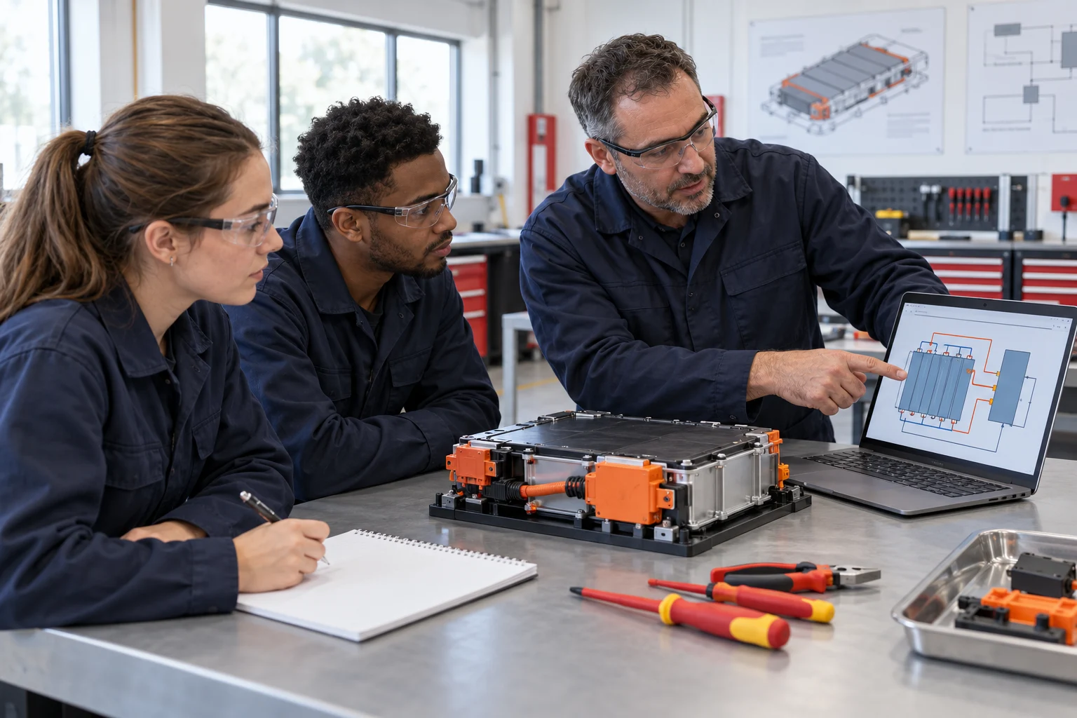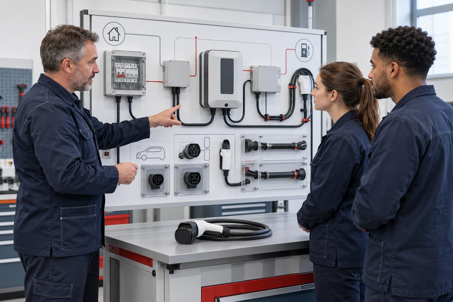


Teach the reasoning behind an electrical diagnosis.
An automotive electrical diagnosis pathway connects circuit reading, instrument selection, observed behaviour and a justified conclusion. Its purpose is to develop technicians who can explain a test decision and retain usable evidence, rather than identify a component from a symptom alone.
This course is intended for vocational automotive programmes and technician training centres. It starts with the circuits actually installed on a selected training bench, then progresses toward a shared-supply complaint and an individual diagnostic report. A broad electrical bench and a focused starting-and-charging bench provide different teaching contexts.
Learners should enter with basic circuit knowledge, unit recognition and supervised workshop measurement experience. Teachers first check these prerequisites through a simple diagram-reading exercise and instrument discussion. Learners who cannot identify a supply, protective element, switch and load need foundation work before an unfamiliar diagnostic problem.
Adapt the learning stages to your syllabus and the vehicle systems in your laboratory. Use the fitted circuits, available test access and approved procedures to agree the practical tasks, teaching hours and assessment resources with your faculty.
Define outcomes that can be observed.
Read the system: trace a documented source-to-load path and identify where a shared supply or protection point connects more than one function. Students should use the supplied diagram and the actual bench labels together, checking that the two references describe the same configuration.
Plan a discriminating check: state at least two plausible explanations for an instructor-defined symptom and choose an observation or permitted measurement that can distinguish them. The first action should have a reason; a long sequence of unrelated checks is not a sound test plan.
Record and interpret evidence: name the instrument, measurement function, reference point, units and operating condition. Compare the result with the approved information for that circuit. A number without its connection method or condition cannot reliably support a conclusion.
Verify and communicate: explain what changed after an authorised correction or instructor reset, repeat the relevant functional check and state any unresolved uncertainty. Each learner produces their own explanation, even when the practical activity is shared by a group.
Six stages from circuit knowledge to diagnostic evidence.
The sequence can span several lessons or be integrated into an existing automotive electrical course. Agree contact hours and progression checks with the faculty; equipment availability should support the chosen teaching method.
01Map the fitted circuits
Build a configuration-specific system picture.
Practical activity
Identify the functions named in the equipment schedule. Trace a selected circuit through its supply, protective devices, controls and load. Compare it with a second circuit and mark any shared path. Where the supplied information is incomplete, record the missing reference instead of inventing a connection.
Evidence to retain
An annotated circuit map that distinguishes fitted components, shared points and information still required.
02Establish normal behaviour
Create a baseline before interpreting a fault.
Practical activity
With the instructor, observe the documented function in its normal operating state. Record the command, expected response and conditions under which the observation was made. If measurement access is included, record a permitted baseline check using the specified instrument and reference point.
Evidence to retain
A baseline sheet containing the function, operating state, method and observation. No universal numerical limit is assumed.
03Select the measurement method
Make the test decision explicit.
Practical activity
Given an exercise brief, explain whether the next step is a visual inspection, a functional observation, a voltage measurement or another supported check. Identify the test point and return reference on the actual diagram. The instructor releases the practical step after reviewing the connection and equipment conditions.
Evidence to retain
A short test plan explaining what each possible observation would mean and why the chosen method can separate the proposed causes.
04Investigate a shared-system symptom
Reason across circuits without guessing a replacement.
Practical activity
Use an instructor-provided case affecting two functions that share a documented supply or protection point. Compare common and local explanations. Perform only checks supported by the bench configuration; a paper case can be used where fault insertion or physical access has not been specified.
Evidence to retain
A hypothesis table linking each candidate explanation to a distinguishing check and the evidence actually available.
05Separate starting from charging
Apply circuit reasoning in a focused context.
Practical activity
On the starting-and-charging teaching scope, compare an engine no-crank complaint with a battery-not-charging complaint. Follow the relevant paths in the supplied diagram and explain which observations belong to each case. Live readings require the configured instruments and an approved operating arrangement.
Evidence to retain
Two separate diagnostic outlines showing the initial symptom, system boundary, first justified check and next decision.
06Complete an individual diagnostic defence
Assess interpretation as well as task completion.
Practical activity
Ask each learner to present the circuit trace, the key evidence, the resulting conclusion and a verification plan. The assessor changes one condition in a follow-up question to establish whether the learner understands the reasoning rather than memorising an earlier group answer.
Evidence to retain
An individual report, retained observations and assessor feedback identifying achieved skills and any task that needs repetition.
Choose the electrical bench by the teaching question.
The Complete Vehicle Electrical Systems Training Bench supports a broad view of fitted circuit relationships. The Automotive Starting and Charging Training Bench provides a focused context for distinguishing two related electrical systems. Neither product title establishes an exhaustive component list or a particular live-testing capability.
A school can start with equipment it already owns. Compare its circuit drawings, accessible points and operating instructions with the required outcomes before adding another bench. A focused station is useful when it provides necessary task access, rather than simply repeating a function already taught adequately.
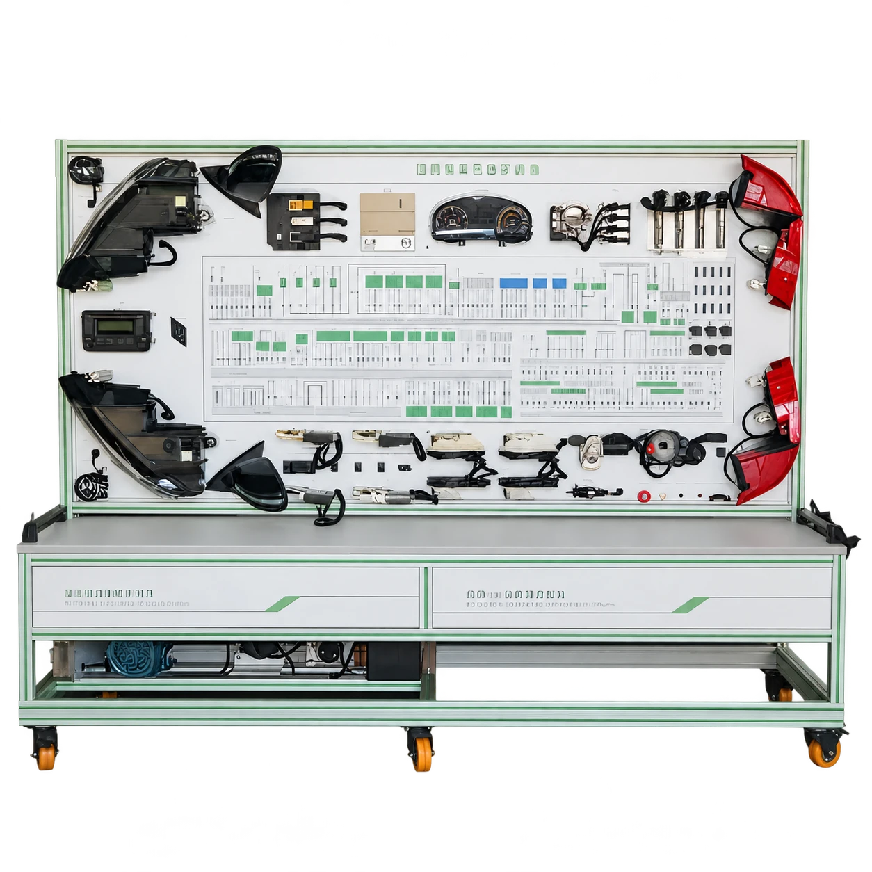
Complete Vehicle Electrical Systems Training Bench
A broad electrical teaching bench for studying the relationships between fitted vehicle circuits, shared supplies and protection.
Teaching roleSystem mapping, source-to-load tracing and cross-system diagnostic reasoning.
View Equipment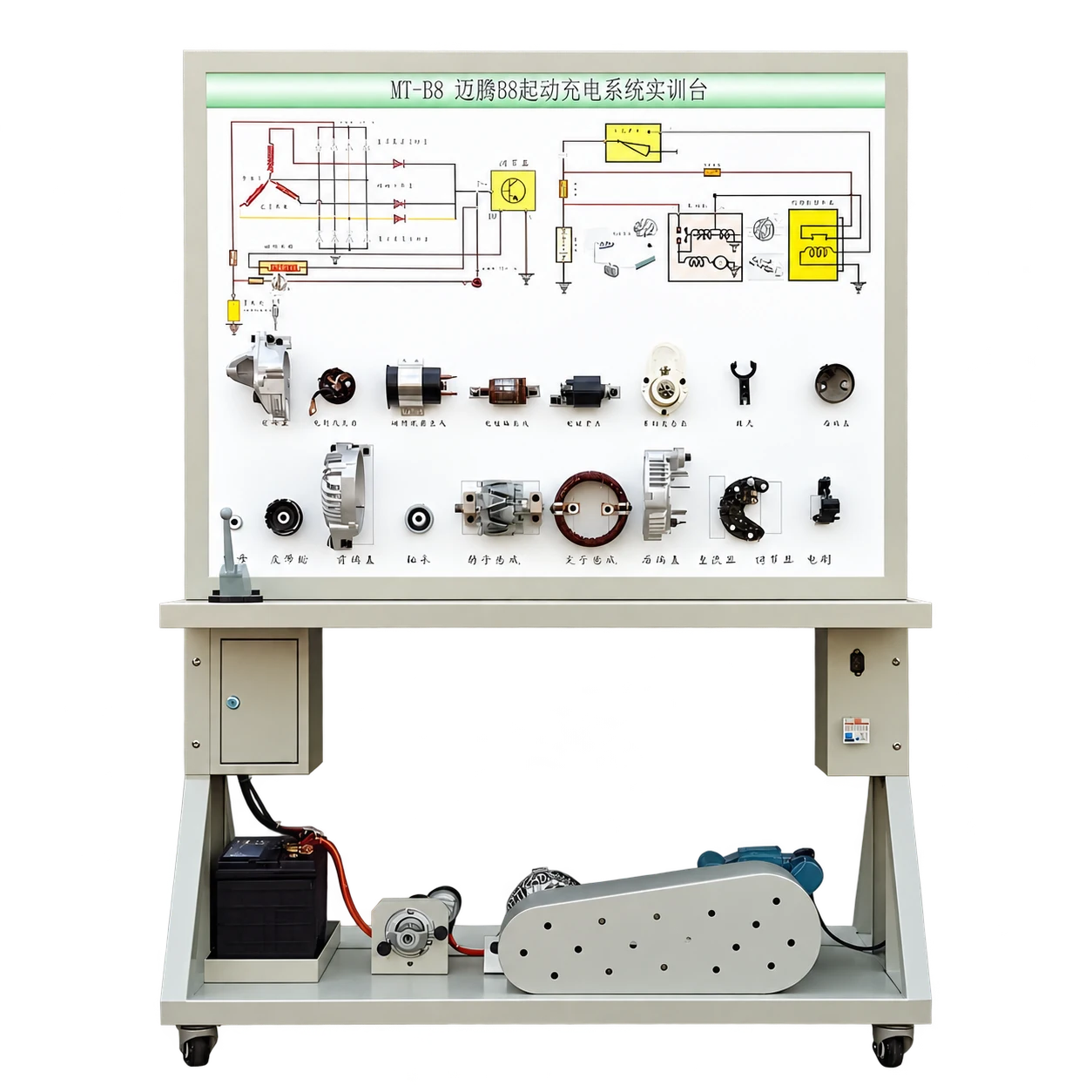
Automotive Starting and Charging Training Bench
A conventional vehicle trainer for separating engine-starting principles from the vehicle battery-charging system.
Teaching roleFocused comparison of a no-crank complaint and a battery-not-charging complaint.
View EquipmentConnect each course unit with a student output.
Use the equipment schedule as a curriculum input. The unit plan should show where learners observe, where they measure and where they explain. That distinction helps teachers prepare the lesson and prevents an observational trainer from being assigned an unsupported practical task.
| Learning unit | Equipment or reference | Evidence produced |
|---|---|---|
| Circuit architecture | Complete electrical bench and its supplied diagrams. | Source-to-load trace, fitted-system list and shared-point map. |
| Measurement planning | Permitted test access, selected instruments and approved procedure. | Connection sketch, units, reference point and decision rationale. |
| Cross-system diagnosis | Two fitted functions with a documented shared relationship. | Common-versus-local hypothesis table and supporting observations. |
| Starting and charging | Focused starting-and-charging bench or an appropriately documented existing system. | Separate case outlines for a no-crank and a charging complaint. |
| Verification and reporting | Task records, instructor reset record and assessment rubric. | Individual report identifying the evidence and remaining uncertainty. |
A sample task: two functions, one shared question.
Illustrative exercise: investigate a case in which two fitted functions do not respond. The instructor selects actual circuits with a documented shared relationship; the exercise does not assume a fault box, a particular vehicle or any fabricated reading.
First, students mark the common and separate circuit paths. They propose one shared explanation and one local explanation, then identify the observation that would most efficiently distinguish them. The teacher reviews the plan before any physical measurement.
Next, students record what was actually observed, including the operating condition and the method used. They explain whether the evidence supports, weakens or leaves a hypothesis unresolved. If a simulated paper case is used, supplied values must be labelled as exercise data.
Finally, each learner writes a verification step and explains why replacing a load would be premature if the shared supply has not been investigated. The purpose is a justified decision, not a predetermined part name.
Open Printable Task SheetAssess measurement quality and decision quality separately.
A learner may arrive at the expected fault name through guessing. Another may select the right measurement but record it poorly. A useful rubric identifies these differences so feedback targets the actual skill gap. The institution sets final weightings and progression requirements.
| Assessment area | Observable performance | Evidence for review |
|---|---|---|
| Circuit interpretation | Trace the fitted circuit and identify relevant shared points. | Annotated drawing matched to the bench configuration. |
| Measurement planning | Choose an appropriate check with a defensible connection method. | Test plan showing possible observations and their meaning. |
| Recording discipline | Retain units, references, conditions and instrument identification. | Measurement sheet or documented functional observation. |
| Diagnostic reasoning | Use evidence to distinguish causes and avoid unsupported certainty. | Hypothesis table, explanation and follow-up questions. |
| Verification | Define and complete the authorised check after correction or reset. | Before-and-after record and an unresolved-items statement. |
Set a specific reassessment task when evidence is incomplete. Repeating an entire course is rarely necessary when the gap is a missing reference point, a poorly justified first check or an inability to distinguish observed behaviour from a proposed cause.
Prepare the diagrams, tasks and instructor reference together.
The course pack should include a configuration-specific circuit set, component identification guide, lesson sequence, student record sheets and an instructor reference. Each document needs a revision or clear link to the equipment configuration it describes. A diagram from a superficially similar vehicle can create a misleading lesson.
Student sheets should ask for the reasoning behind a test, not only a final reading. Instructor materials should specify the intended observations, acceptable alternative approaches and the evidence required before progressing. Where a fault exercise is supported, distinguish the controlled teaching condition from faults or damage that must not be created.
Short demonstration clips can show diagram orientation, locating a permitted test point or completing a record. The clip should name the actual station and task. Optional virtual preparation can rehearse decisions, while the physical lesson still checks instrument handling and connection discipline.
BTKX course development can help your faculty develop task sheets, teaching resources and assessment materials for the selected circuits. Specify the required formats, languages, editing rights and delivered examples in the course-development schedule.
Plan the laboratory around active diagnostic work.
Begin with the number of learners who must personally demonstrate circuit tracing and measurement. Group observation is useful for an introduction, but one person holding the probes does not show that every group member can select a connection or explain a reading.
Give rotating roles a learning purpose: one learner interprets the diagram, one proposes the check, one performs the authorised action and one maintains the record. Change roles for a new circuit or case, then use an individual explanation to verify understanding. Determine group size from visibility, access and supervision rather than an arbitrary students-per-bench ratio.
Keep diagrams, task sheets and instruments available at the station. Plan cable routing, display visibility and a clear place for the measurement record. Where the starting-and-charging configuration uses moving assemblies, a battery or a running engine, its specific protective and installation provisions form part of room planning.
A simple procurement review should record the required circuit list, test points, instruments, fault-exercise method, electrical supply and operating mode. Confirm any ventilation requirement for the selected arrangement. The vocational school solution can help relate these decisions to the wider laboratory programme.
Rehearse the questions teachers will ask at the bench.
Teacher familiarisation should include completing a real task sheet, checking it against the instructor reference and discussing more than one defensible diagnostic approach. The strongest coaching questions ask what a proposed check can establish and what it cannot.
Use a teach-back exercise: a teacher briefs the selected task, observes a colleague’s measurement plan and gives feedback using the draft rubric. This identifies confusing labels, missing circuit references and instructions that rely on unwritten knowledge before a student group encounters them.
Agree responsibility for baseline records, exercise reset, tool checks and document updates. If the school changes a fitted assembly or diagram, review the task and assessment reference together. Teacher training should be scoped around the selected equipment and required teaching activities.
Deliver a documented diagnostic teaching capability.
Define: review the syllabus, learner level, existing circuits and intended evidence. Produce an outcome-to-equipment map and identify any tasks that need a dedicated bench, instrument or resource.
Configure: agree the fitted-system schedule, diagrams, test access, operating arrangement and included instruments. Confirm whether each exercise uses observation, physical measurement, a controlled teaching fault or supplied case information.
Develop and demonstrate: review sample task sheets with the faculty, then demonstrate the accepted tasks during commissioning and teacher preparation. Record the actual configuration and any dependencies that affect repeatability.
Accept and maintain: verify that the listed diagrams, procedures, resources and agreed functions are available. Retain the course resource inventory, training record and support responsibilities. This establishes what the institution can teach at handover and what requires a later extension.
Adapt vehicle context, terminology and assessment requirements.
Choose circuit examples relevant to the vehicles and qualifications taught by the institution. A starting circuit, body function or network arrangement differs between architectures; a local course should identify the actual reference system instead of assuming that one diagram represents the entire vehicle population.
Confirm translation scope separately for circuit labels, student sheets, instructor answers, software interfaces and training sessions. Retain recognised component identifiers where translating them would make comparison with service information harder. Have a technically competent local teacher review terminology in context.
Map the proposed outcomes to the institution’s current programme documents and record the source and version of any named competency requirement. This is evidence of a curriculum review, not proof of qualification recognition. The school remains responsible for its approved assessment and credential arrangements.
Develop digital resources around the diagnostic task.
BTKX’s Guangdong Corolla fault-diagnosis simulation case illustrates the importance of selecting a vehicle context and teaching tasks together. It can inform discussion of digital preparation, fault reasoning and evidence review.
For your course, request a resource example matched to the selected bench and review the agreed diagnostic task with your faculty. Confirm the vehicle circuits, software content and practical assessment requirements in the project scope.
Questions Before You Configure the Pathway.
Does a complete electrical bench include every vehicle circuit?
No. The accepted circuit schedule defines the fitted systems. Compare that list, the drawings and available test access with the syllabus before assigning practical tasks.
Can learners perform live measurements on every bench?
Only where the selected configuration provides the required operating arrangement, instruments, access and approved procedure. Otherwise a lesson can use circuit interpretation, observation or clearly labelled case information.
Is the starting-and-charging trainer an EV charging trainer?
No. Its charging topic concerns the conventional vehicle battery-charging system associated with engine operation. EV charging equipment addresses a different system and course scope.
Does this pathway include CAN diagnosis?
CAN can be an extension when the selected equipment, network documentation and tools support it. The core pathway does not assume a CAN interface, analyser, fault function or network architecture on either bench.
How can existing laboratory equipment be used?
Start with its actual circuits, diagrams and permitted measurements. Map these to the required outcomes, then add equipment or resources only where a documented teaching gap remains.
What makes a diagnostic assessment stronger than a fault-name quiz?
It retains the circuit trace, the reason for the selected check, the recorded evidence and the verification decision. An individual explanation helps distinguish reasoning from a memorised or shared answer.
Explore Further
Equipment, Services & Project Details.
Explore product specifications, teaching support and project examples to help plan the equipment and course resources for your institution.