

Baitong Kexin
Contact

EV Battery Assembly & BMS Training System

Model: BT-NEV2-T028

An integrated practical platform for LFP battery assembly, BMS measurement and guided fault diagnosis.

EV Battery Assembly & BMS Training System

EV Battery Assembly & BMS Training System
Battery Assembly
≥60 V LFP
Single Cell
3.2 V / 30 Ah
BMS Connection
CAN-H / CAN-L
Workstation dimensions
≥1,630 × 780 × 1,730 mm (L × W × H)
Request This Configuration
On This Page Overview

Product Overview

The Baitongkexin BT-NEV2-T028 is an EV battery training system for vocational colleges, technical institutes and automotive training centers. It brings LFP battery assembly, measurement instruments, a manual fault-setting interface and BMS monitoring software into one supervised practical station.

Course areas: EV battery assembly and commissioning courses, BMS measurement and guided fault-diagnosis training, Battery service, inspection and measurement practice, Practical assessment and skills-competition preparation using the confirmed software configuration.

Suitable for: Vocational colleges, Technical institutes, Automotive training centers.

Core Learning Functions

The system connects battery construction with practical assembly records, physical measurements and BMS information. Learners can compare measured cell and pack data with the software display, complete approved assembly tasks and use circuit evidence to explain instructor-selected faults.

Cell Testing and Sorting

Measure cell voltage and internal resistance, record the values and explain the resulting sorting decision.

Module and Pack Assembly

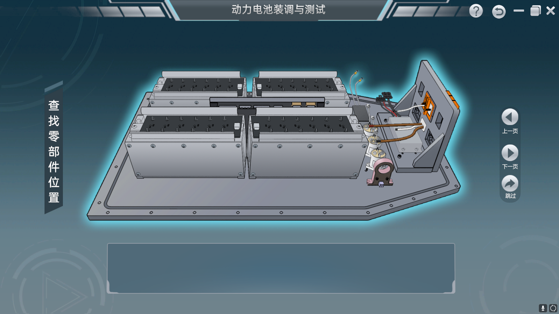
Identify, disassemble, assemble and inspect battery components against the approved work sequence.

BMS Data Interpretation

Compare physical measurements with cell, pack, temperature, current and state-of-charge information shown in the BMS software.

Electrical Fault Diagnosis

Link symptoms, circuit information and permitted measurements to an instructor-selected fault condition.

Practical Training Tasks

  • Measure cell voltage and internal resistance
  • Sort individual cells using recorded measurements
  • Assemble, mark, commission and inspect a battery module
  • Disassemble, assemble, commission and inspect the traction-battery pack
  • Remove, install and measure contactors, current sensors and the precharge resistor
  • Remove and install the AC charging interface, manual service disconnect and high-voltage connectors
  • Check thermal-management and PACK air tightness
  • Install the BMS and connect the documented high- and low-voltage harnesses
  • Read pack, cell, temperature, SOC, relay, charger and insulation data in the BMS software
  • Diagnose instructor-selected contactor, precharge-resistor, sensor, cell-sampling, insulation-monitoring and charging-circuit faults
  • Complete charge and discharge testing within the confirmed equipment configuration

Equipment Composition

  • Battery Assembly Workstation

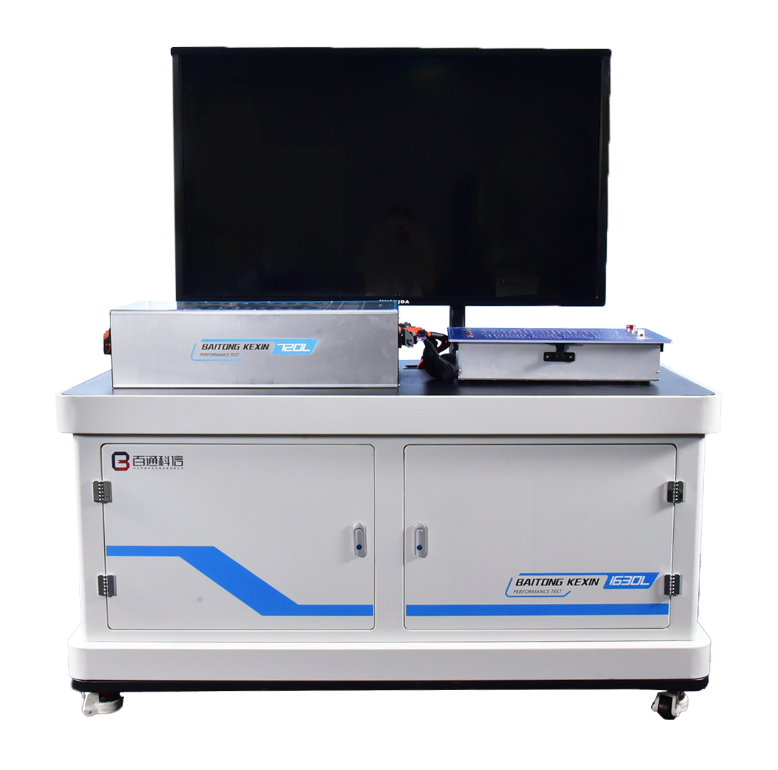
    The metal workstation provides an upper working area for battery-component measurement, assembly and commissioning. Its lower section uses divided drawers and fitted inserts for the specified insulated tools, instruments and harnesses.

  • LFP Training Battery and Charging Hardware

    The documented battery assembly includes cells, modules, current and temperature sensing, main and precharge relays, a precharge resistor, service disconnect, onboard charger, AC charging interface, cooling-system interface, BMS, and high- and low-voltage harnesses.

  • Manual Fault-Setting and Measurement Box

    The fault box works with the battery and BMS circuits. It supports instructor-selected open-circuit, intermittent-connection, short-circuit and crossed-line conditions across the documented power, sensing, relay-control and insulation-monitoring circuits, with insulated measurement terminals for diagnosis.

  • Insulated Tools and Test Instruments

    The documented configuration includes an insulated metric tool set and instruments for battery internal resistance, insulation resistance, grounding resistance and general electrical measurement. The fitted lower drawers provide dedicated storage for the tools, CAN interface and associated test accessories.

  • Teaching Display and BMS Software

    The teaching display and BMS software present pack voltage and current, cell-voltage and module-temperature data, SOC, relay status, charger data, insulation information and detected fault information through the documented CAN-H and CAN-L connection.

Technical Specifications

Specifications apply to the documented configuration. The final product and project configuration is confirmed in the technical schedule.

The following values define the verified configuration. Symbols such as ≥, ≤ and < retain their specified meaning.

EV Battery Assembly & BMS Training System — Technical Specifications
Workstation dimensions≥1,630 × 780 × 1,730 mm (L × W × H)
Battery-pack dimensions884 × 530 × 230 mm
Nominal battery voltage≥60 V
BMS operating voltage range9–36 V DC
BMS operating temperature range-40–85 °C
BMS storage temperature range-40–125 °C
BMS operating humidity0–95%
Cell-voltage detection range0–5 V
Cell-voltage sampling accuracy≤5 mV
Cell-voltage sampling interval≤100 ms
Total-voltage detection accuracy<1%
Temperature measurement range-40–125 °C
Temperature detection accuracy±1 °C
Current detection range≤75 A
Charger full-load operating altitude≤3,000 m
Charger storage temperature-40–80 °C
Charger ambient temperature-20–55 °C normal output; 55–75 °C derated output
Charger relative humidity0–95%
Charger specification75 V / 10 A
Input voltage≥220 V AC
Operating frequency50/60 Hz
Output voltage≥75 V DC
Output current≤10 A
Output power≥800 W
Voltage regulation accuracy≤1%
Output-voltage ripple (P-P)≤1%
Efficiency≥0.93
Input over-voltage protection260 V AC
Input under-voltage protection176 V AC
Over-temperature protection / recovery80 °C / 60 °C
Output over-voltage protection≥80 V DC
Output under-voltage protection10 V battery-pack voltage
Input-to-output insulation resistance≥100 MΩ at 1,000 V DC
Output-to-enclosure insulation resistance≥100 MΩ at 1,000 V DC
CommunicationCAN 2.0
Auxiliary power supply≤12 V / 3 A
Ingress protectionIP65
Operating noise≤60 dB
Cell voltage3.2 V
Cell capacity30 Ah
Temperature-sensor resistance at room temperature1,000 Ω
High-voltage relay contact-current rating0–100 A
High-voltage relay coil voltage12 V
High-voltage relay maximum operating voltage0–220 V
Precharge resistance100 Ω
Precharge-resistor power100 W
Teaching-display size≤55 in
Insulated-tool voltage rating1 kV
Battery-resistance tester resolution0.1 mΩ
Insulation-resistance measurement2,000 MΩ
Insulation tester DC-voltage range0 to ±1,000 V DC
Insulation tester AC-voltage range30–750 V AC
Insulation tester short-circuit currentApprox. 1.3 mA
Insulation tester weightApprox. 600 g
Ground-resistance measurement range0–2,000 Ω
Ground-voltage measurement range0–200 V
Multimeter voltage range400 mV–1,000 V
Multimeter current range400 μA–10 A
Multimeter resistance range400 Ω–40 MΩ
Multimeter frequency range9.999 Hz–9.999 MHz
Relay-status channels≥10 with one-button control
Maximum software resolution1,920 × 1,080 px
Scenario-introduction animation≥15 s

Teaching Resources and Use

Battery Assembly and Testing Simulation

The configured package includes companion virtual-simulation software with demonstration, teaching and assessment modes. It supports guided task flow, tool selection, timed practice, scoring and review for the documented battery assembly, measurement and fault-diagnosis activities.

Curriculum and Task Materials

Matching vocational teaching material covers battery recognition, pack assembly and commissioning, BMS measurement, performance experiments and fault diagnosis. Language, licensing, document format and the final resource list are confirmed in the technical schedule.
Configuration and Ordering

Reference Laboratory Quantity

1 unit

This quantity belongs to the reference laboratory equipment schedule. Confirm the quantity for your project in the quotation.

Configuration and Procurement

Confirm the final battery configuration, accessories, software version, resource languages, room services and installation responsibilities in the signed technical schedule. Any external lifting, charging, ventilation or instructor-support requirements should be itemized in the quotation.

Details for Your Inquiry

Share the learner level, class size, station quantity, required assembly and diagnostic tasks, and destination electrical conditions so the product, software, resources, delivery scope and applicable safety procedures can be defined for the project.

Product Questions

What equipment is included in the documented configuration?

It includes the battery assembly workstation, LFP training battery, insulated tool and instrument set, teaching display, manual fault-setting box and BMS software described on this page. The final accessory, software and resource list is confirmed in the technical schedule.

What can learners practise on this system?

Learners can complete battery-cell measurement and sorting, module and pack assembly, component measurement, BMS data reading, guided fault diagnosis, air-tightness checks and charge-discharge testing under instructor supervision.

Does the system replace a dedicated battery performance-analysis platform?

No. This system focuses on battery assembly, commissioning, measurement and BMS-related diagnosis. Institutions requiring extended charge-discharge cycling and performance-data analysis should also review the dedicated battery performance test and analysis platform.

Which project details should be confirmed before ordering?

Confirm the required practical tasks, class size, station quantity, room conditions, electrical supply, destination requirements, software language and licensing, teaching-resource package, and any installation or instructor-training services required in the contract scope.