Baitong Kexin
Contact

Motor Assembly & Testing

Drive Motor Assembly & Performance Training

Connect repeated motor assembly with resolver alignment, dimensional checks and measured torque-speed performance. Select compatible teaching and test stations for the required tasks.

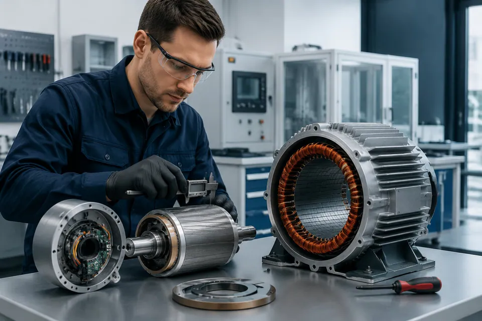
A learner measuring an exposed drive motor assembly
Illustrative motor inspection scene showing a rotor measurement alongside the separated stator and end cover.

The Training Route

Assemble, Align and Test the Drive Motor.

Follow the motor from mechanical assembly and resolver alignment through dimensional and magnetic checks to measured operating performance.

  1. Assemble the Motor

    Learner Practice

    Practise stator, rotor and end-cover assembly with the specified fixtures, fastening sequence and inspection tools.

    Evidence of Learning

    Document the assembly checks required before the motor proceeds to a powered test.

  2. Verify Alignment

    Learner Practice

    Fit and zero the resolver, then record coaxiality and magnetic-flux measurements using a repeatable procedure.

    Evidence of Learning

    Explain how the alignment and measurement records support the assembly inspection.

  3. Review Operating Performance

    Learner Practice

    Use a compatible performance station for approved motor tests and record the load, temperature and measurement conditions.

    Evidence of Learning

    Interpret torque-speed performance and compare results obtained under documented conditions.

The Equipment Combination

Connect the Tasks with the Right Equipment.

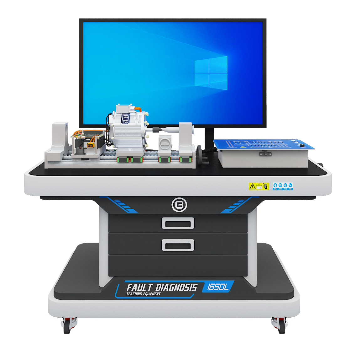
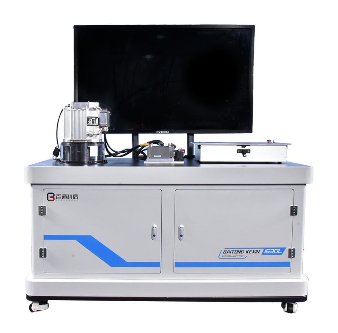
Use T036 for motor assembly, resolver alignment and mechanical checks, with a compatible T076 station for operating-performance exercises. The selected motor, controller, coupling, supply and load define the permitted test envelope.

Technical Configuration and Operating Limits
ItemTeaching Configuration
Assembly motor, T036PMSM; 80 V DC; rated power ≤15 kW / peak power ≤29 kW; rated torque ≤30 N·m / peak torque ≤110 N·m; peak speed ≤7,500 r/min; class H insulation, S9 duty in the reference configuration.
Assembly control and measurementCAN-H/CAN-L and USB-CAN interface; printed circuit panel with insulated 2 mm test terminals. Controller voltage range is a subsystem specification, not permission to exceed the motor rating.
Performance station, T076Test equipment rated power ≥11 kW; 380 V AC three-phase five-wire supply. Confirm selected motor, coupling and load configuration.
Dynamometer envelopeRated speed ≥2,000 r/min; maximum speed ≥4,000 r/min; rated torque ≥30 N·m; measurement range ≥50 N·m. Confirm exact ordered limits.
Measurement specificationSpeed accuracy ±0.1% full scale; torque accuracy ±0.2% full scale; speed resolution 0.1 r/min; data update interval 20 ms.
Teaching tasksStator and rotor assembly, end-cover installation, resolver fitting and zeroing, magnetic flux density and coaxiality measurement, followed by approved performance tests.
Mechanical preparationConfirm assembly fixtures, press and measuring tools, fastening procedures, guarding and the inspection criteria used before energizing.

From Equipment to Teaching

Build a Repeatable Teaching Routine.

Move groups from assembly inspection and alignment records to approved powered tests, using common measurement procedures and documented conditions for comparisons.

Verified Resolver Alignment

Make resolver fitting, zeroing and verification a scored part of motor assembly. Learners complete the model-specific inspection and alignment procedure before any powered test, giving the instructor a clear record of readiness.

Measured Assembly Quality

Use the specified fixtures and fastening procedure to support correct end-cover seating and alignment. Record coaxiality and clearance checks, and investigate an out-of-tolerance assembly before allowing it to proceed to a powered test.

Repeatable Flux Measurements

Define a repeatable probe position, orientation and instrument procedure for magnetic-flux measurements. Ask each group to explain its recorded values in relation to the motor model and approved torque-speed data, making comparisons meaningful.

Comparable Performance Curves

Use a matched load system and document setup, temperature and load conditions for each run. Review calibration, sensor ranges and the T076 measurement specification before asking learners to interpret differences between their recorded performance curves.

Full Instructor Notes and Scope to Confirm

Connect Assembly Quality with Measured Performance

Pair an accessible assembly unit with the fixtures and instruments needed for resolver, coaxiality and magnetic-flux checks. Use each inspection record to prepare for the next stage of the course.

A compatible performance station connects the completed assembly with torque-speed results. Agree the motor, controller, coupling, supply and load envelope before planning powered exercises.

Confirm These Requirements Separately

  • A product-development dynamometer assumed to cover motor ratings beyond the ordered test envelope
  • A course solely about brushed DC or induction-machine assembly
  • Industrial motor remanufacturing production equipment

Resolver Zero Position Is Incorrect

What to Watch For
The reassembled motor may vibrate, draw abnormal current or fail to start.
Possible Cause
Resolver installation and alignment have not been verified against the model-specific procedure.
Teaching Response
Make resolver installation and verification a scored task. Complete the approved inspection and alignment process before any powered test.

Rotor and Stator Are Misaligned

What to Watch For
Uneven clearance, contact noise or abnormal heating appears after assembly.
Possible Cause
End-cover seating, bearing alignment or fastener sequence is inconsistent.
Teaching Response
Use the specified fixtures and assembly procedure, then record coaxiality and clearance checks. Stop and investigate an out-of-tolerance assembly rather than using a powered run to diagnose contact.

Flux Measurements Are Inconsistent

What to Watch For
Groups record different magnetic flux values for the same rotor and cannot explain the difference.
Possible Cause
Probe orientation, position or measurement reference changes between groups.
Teaching Response
Define a repeatable measurement position and instrument procedure, then relate the recorded values to approved torque-speed data and the motor model.

Performance Curves Cannot Be Compared

What to Watch For
Efficiency or torque-speed curves vary without a recorded change in the exercise.
Possible Cause
Setup, temperature, load profile, instrumentation or calibration differs between runs.
Teaching Response
Use a matched load system and documented test conditions. Review calibration, sensor ranges and the T076 accuracy specification before interpreting differences between student results.

Project Experience & References

Standards and Motor Assessment Tasks

Use the named competition’s dated device and task files alongside applicable 1+X assessment rubrics for the selected motor configuration.

Connect the Classroom with a Delivered Practice Center

A drive motor performance test bench was delivered to the Beijing Commercial School open industry-education practice center. The company also supplies e-drive competition equipment and a motor assembly simulation title for procedure rehearsal.

The documented competition simulation package includes ≥80 operation steps per project and reference-matched fault logic. Confirm the licensed title and hardware version for the present course.

Documents to Review for Your Project

Request Range-Specific Measurement Evidence

The T076 specification states torque accuracy ±0.2% full scale, speed accuracy ±0.1% full scale and 0.1 r/min speed resolution. These expressions must be interpreted against the actual selected sensor range.

Request the current specification sheet, measurement and calibration documents, a demonstration report and the compatible motor/load schedule. Record the confirmed speed and torque limits in the acceptance plan.

Reference Documents and Project Basis

  • Task files of the National New Energy Vehicle Key Technology Skills Competition; the company’s documented record includes designated equipment partnership in the 2020 edition.
  • The exact e-drive competition equipment specification for the selected event; current product scope must be matched to the event’s dated technical files.
  • Applicable assessment rubrics for the 1+X New Energy Vehicle Assembly and Testing certificate.

Application FAQs

Plan Your Training Project.

Can T076 test every peak condition of the T036 motor?

Do not assume that. The T036 reference specification lists rated power ≤15 kW and peak power ≤29 kW, while T076 has its own speed, torque, power and coupling limits. The supplier must confirm a compatible test configuration and approved operating envelope for the intended exercises.

Why not use only an unpowered cutaway motor?

A cutaway is useful for component recognition. Assembly competency also requires alignment checks and evidence that the completed unit meets inspection criteria. A compatible performance station adds measured operating results where the course calls for them.

How should practical work be assessed?

Record the assembly inspections, resolver verification, coaxiality and flux measurements, followed by permitted performance data. Use the same documented conditions for each group and keep virtual simulation scores separate from observed physical competence.