On This Page
Automotive electrical training is most effective when students can see the circuit, build it, measure it and explain its behavior. Build that progression with defined circuit tasks, approved measurement points and an assessment record. Moving directly from a schematic to whole-vehicle diagnosis can leave gaps in instrument selection, circuit reasoning and the verification of a fault conclusion.
Establish the Fundamentals on Accessible Circuits
Begin with power supply, protection, switching and load behavior. Students should be able to identify terminals, follow current paths and predict the result of an open circuit, short circuit or excessive resistance before using a meter.
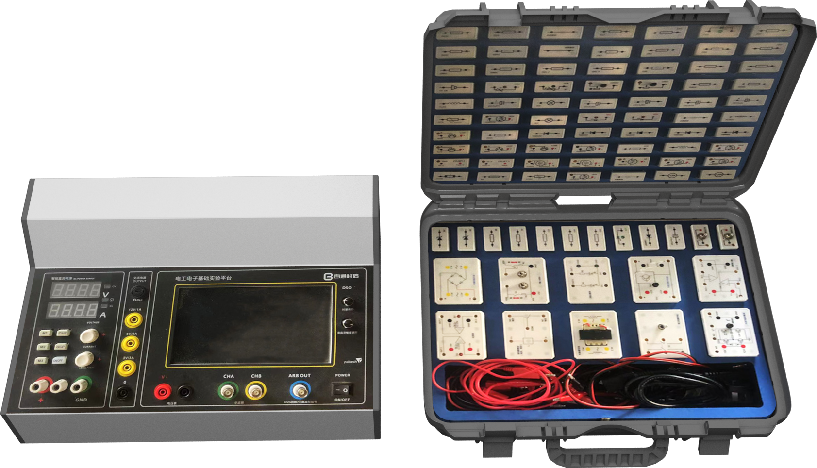
A modular fundamentals platform gives instructors a controlled environment for this work. Protected test points and clearly organized components make repeated practice possible without turning the exercise into a purely abstract diagram.
Teach Measurement as a Decision Process
Instrument use should always answer a technical question. Instead of instructing students to “measure voltage,” define what they are trying to confirm: supply availability, voltage drop, switching state, ground integrity or sensor output.
A useful measurement sequence is:
- interpret the circuit and define the expected state;
- select the instrument and range;
- choose safe measurement points;
- compare the result with the expected value;
- decide what to test next.
Introduce Faults Without Losing Control
Repeatable fault insertion allows every student group to diagnose the same condition and enables the instructor to assess the reasoning process. Faults should be technically meaningful, non-destructive and traceable to the circuit being studied.
The assessment should consider more than the final answer. Safe tool use, test-point selection, measurement interpretation and verification after repair are all part of practical competence.
Connect the Bench to the Vehicle
Once students understand the electrical logic on an accessible platform, the same method can be transferred to vehicle systems. Wiring diagrams become easier to interpret because the learner has already observed how relays, protection devices, loads and control signals behave.
This progression—from visible fundamentals to integrated vehicle diagnosis—helps institutions build a more reliable foundation for later NEV and intelligent-vehicle courses.
Assess the Diagnostic Path, Not Only the Final Answer
| Stage | Learner Evidence | Instructor Check |
|---|---|---|
| Circuit interpretation | Identified supply, protection, control and load path | Is the explanation tied to the actual diagram? |
| Measurement plan | Expected reading and permitted test point | Does the instrument and range suit the approved exercise? |
| Observation | Recorded value and system condition | Can another group understand how the reading was obtained? |
| Diagnosis | Conclusion linked to the readings | Are alternative explanations considered? |
| Restoration | Approved reset and verification record | Has the system returned to the required teaching state? |
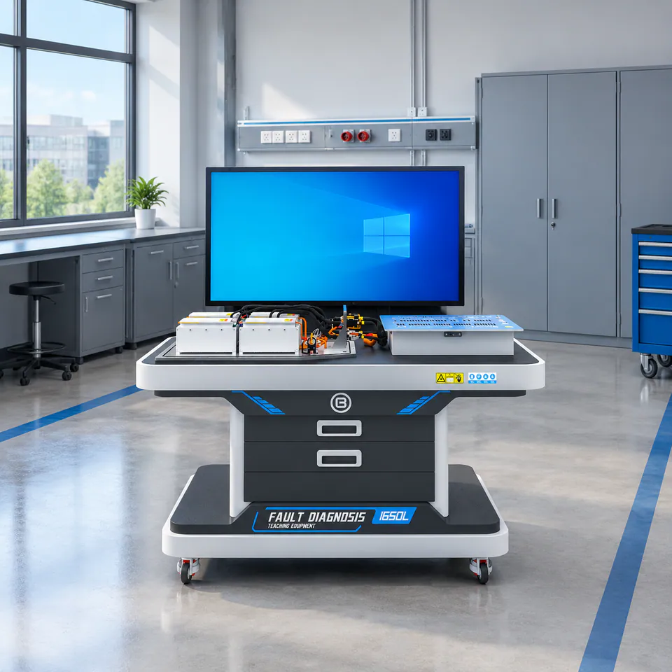
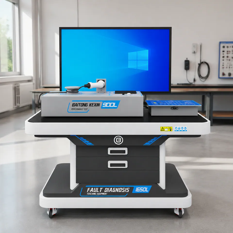
Use instructor-selected faults within the equipment’s validated scope. The T136 whole-vehicle workstation has a board design capacity of at least 256 paths, but its delivered vehicle circuits and exercises are specified separately. The same principle applies to foundation modules: confirm the actual module, instrument and task schedule rather than treating a catalog count as a lesson plan.
Compare the electrical fundamentals platform with the whole-vehicle diagnosis scenario. Curriculum development can connect those two levels with task sheets and assessment criteria.

Editorial Responsibility
Baitong Kexin
Published by Beijing Baitong Kexin Machinery Equipment Co., Ltd. Product limits follow the current model documentation; project scope and acceptance requirements are confirmed in the quotation.