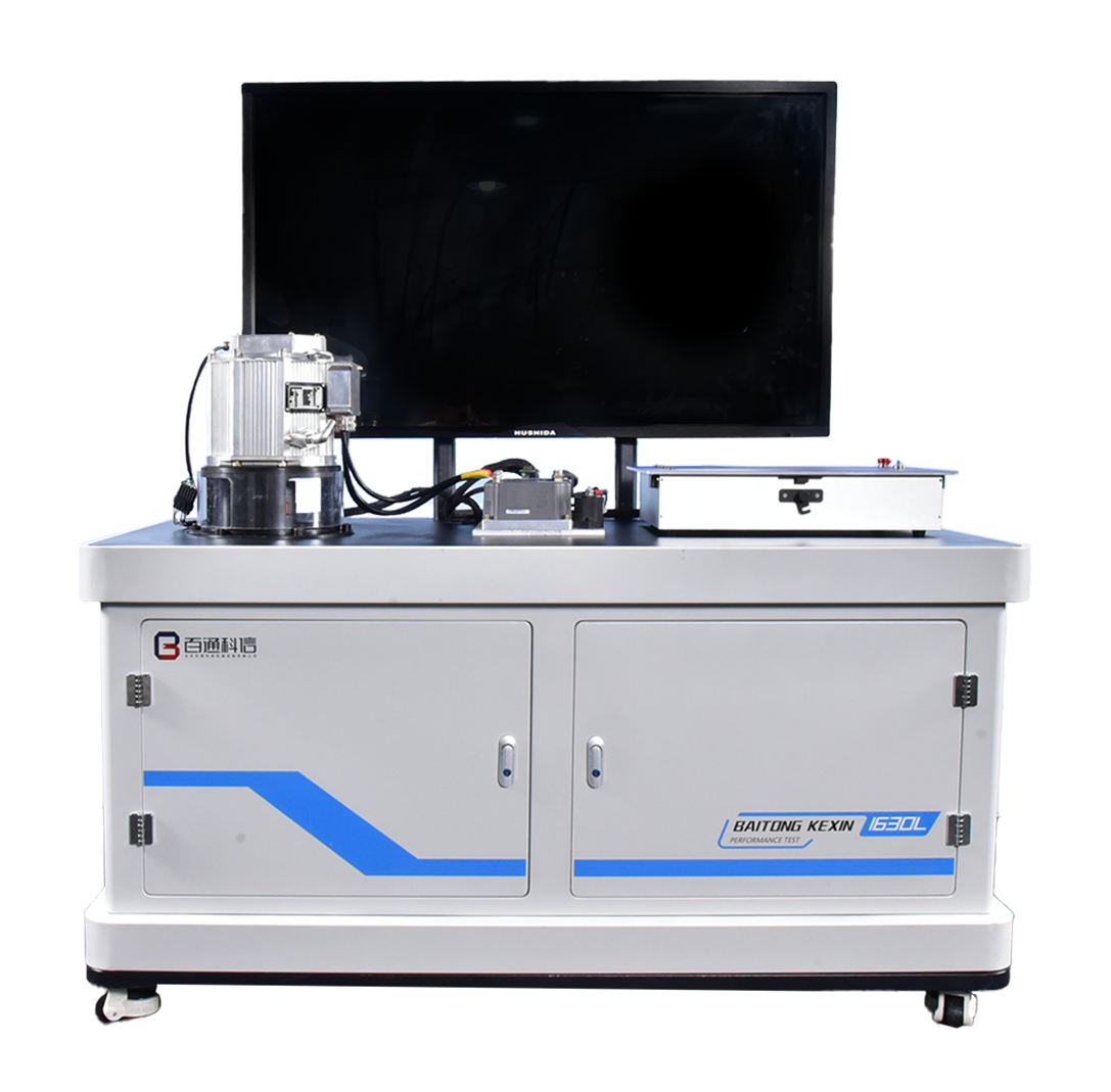

Drive Motor Assembly & Testing Training System
Model: BT-NEV2-T036
A practical station for permanent magnet motor assembly, resolver adjustment, mechanical inspection and guided drive-circuit diagnosis.
- Motor Type
- Three-Phase PMSM
- Assembly Fixture
- Hand-Operated
- Controller Communication
- CAN-H / CAN-L
- Workstation dimensions
- ≥1,630 × 780 × 1,730 mm (L × W × H)
On This Page Overview
Product Overview
A practical station for permanent magnet motor assembly, resolver adjustment, mechanical inspection and guided drive-circuit diagnosis.
Core Functions
The system links drive-motor construction with controller connections, electrical measurement and service reasoning. Learners can complete supervised assembly tasks, inspect documented signals and use evidence from the configured circuits to explain a fault condition.
Practical Training Tasks
- System test
- Insulation-resistance test
- Resistance test
- Fault-box practice
- Insulated-tool and instrument practice
- Drive-motor disassembly and assembly
- insulation resistance measurement
- temperature sensor insulation resistance measurement
- Electrical measurement practice
- Traction-battery test
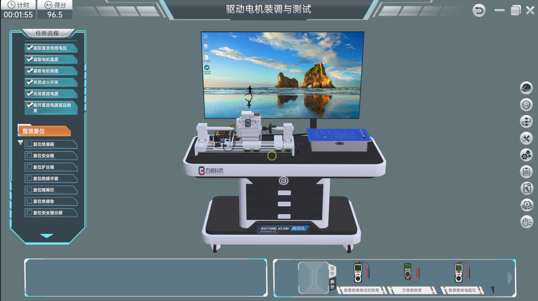
- Virtual simulation for operating procedures, fault detection and guided diagnosis
- Drive motor testing
- IG-circuit fault diagnosis and service inspection
- General fault diagnosis and service inspection
- Coil fault diagnosis and service inspection
- Temperature-sensor fault diagnosis and service inspection
- High-voltage protection practice
- High-voltage safety-protection procedures
- Drive-motor fault diagnosis and service inspection
Equipment and Instruments
Drive motor metal bench frame
Drive motor
Permanent-magnet synchronous motor controller
Teaching display
Fault box
Insulated tool set measurement instruments
Drive-motor controller software
Technical Specifications
Motor and controller values below describe the reference configuration, not the electrical input or safe operating limits of the complete station. Confirm the final component ratings, external DC supply and installation requirements in the model-specific quotation.
The following values define the verified configuration. Symbols such as ≥, ≤ and < retain their specified meaning.
| Workstation dimensions | ≥1,630 × 780 × 1,730 mm (L × W × H) |
|---|---|
| Motor dimensions | 320 × 190 mm (L × diameter) |
| Motor rated voltage | 80 V DC |
| Motor rated power | ≤15 kW |
| Motor peak power | ≤29 kW |
| Motor rated torque | ≤30 N·m |
| Motor peak torque | ≤110 N·m |
| Motor peak speed | ≤7,500 r/min |
| Motor duty | S9 |
| Ingress protection | IP67 |
| Motor phases | 3 |
| Motor-controller dimensions | ≥260 × 200 × 110 mm (L × W × H) |
| Motor-controller rated voltage | 80–360 V DC |
| Motor-controller peak current | ≤110 A / 30 s |
| Motor-controller control voltage | 0.5–30 V DC |
| Motor-controller output frequency | <300 Hz |
| Motor-controller communication | CAN |
| Motor-controller weight | 5.4 kg |
| Motor-controller maximum efficiency | 93%, excluding motor |
| Teaching-display size | ≤55 in |
| Insulated-tool voltage rating | 1 kV |
| Insulation-resistance measurement | 2,000 MΩ |
| Insulation tester DC-voltage range | 0 to ±1,000 V DC |
| Insulation tester AC-voltage range | 30–750 V AC |
| Insulation tester short-circuit current | Approx. 1.3 mA |
| Insulation tester weight | Approx. 600 g |
| Ground-resistance measurement range | 0–2,000 Ω |
| Ground-voltage measurement range | 0–200 V |
| Multimeter voltage range | 400 mV–1,000 V |
| Multimeter current range | 400 μA–10 A |
| Multimeter resistance range | 400 Ω–40 MΩ |
| Multimeter frequency range | 9.999 Hz–9.999 MHz |
| Tesla-meter display | 3½-digit LCD; maximum reading 1,999 |
| Tesla-meter ranges | 200/2,000 mG; 20/200 mT |
| Tesla-meter operating temperature | 0–40 °C |
| Tesla-meter operating humidity | ≤80% |
| Tesla-meter weight | 260 g |
| Tesla-meter dimensions | 160 × 75 × 34 mm (L × W × H) |
| Maximum software resolution | 1,920 × 1,080 px |
| Scenario-introduction animation | ≥15 s |
Configuration and Ordering
Reference Laboratory Quantity
1 unit
This quantity belongs to the reference laboratory equipment schedule. Confirm the quantity for your project in the quotation.
Configuration and Procurement
Confirm the final motor and controller configuration, insulated tools, instruments, software version, room conditions and installation responsibilities in the signed technical schedule. Any external power, lifting or instructor-support requirements should be itemized in the quotation.
Details for Your Inquiry
Share the learner level, class size, required assembly and diagnostic tasks, and destination electrical conditions so the equipment, software, delivery scope and applicable safety procedures can be defined for the project.
Product Questions
What practical work does this system support?
The configured scope includes drive-motor disassembly and assembly, insulation and resistance measurement, controller-circuit study and guided fault diagnosis.
Is this the same as a motor performance test bench?
No. This system focuses on assembly, measurement and diagnosis. Controlled torque, speed and performance analysis require the dedicated drive-motor performance test platform.
Which items should be confirmed in the quotation?
Confirm the motor, controller, fault box, insulated tools, instruments, software, lifting provisions, room services and documentation required for the planned course.
Continue Exploring
Related Products
Compare the stated teaching roles below. Product connections, included accessories and software licenses are confirmed in the selected configuration.