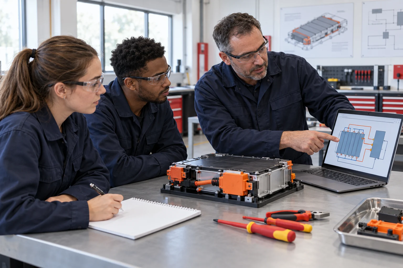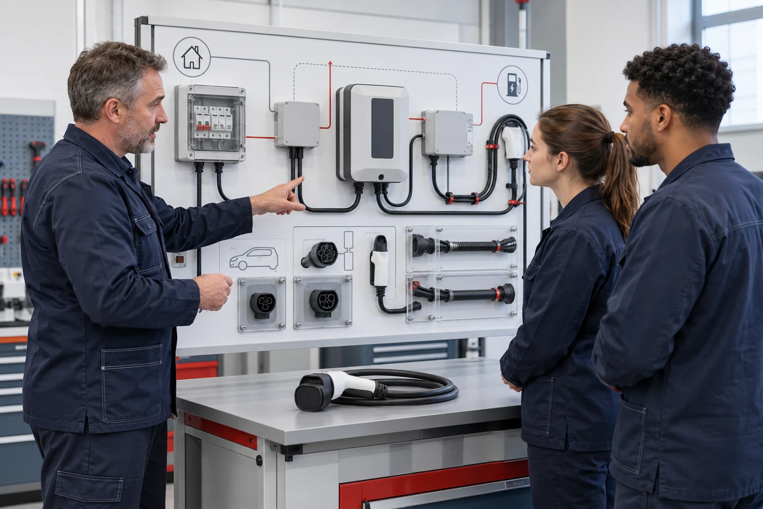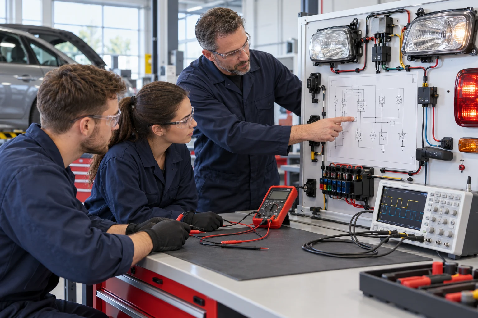

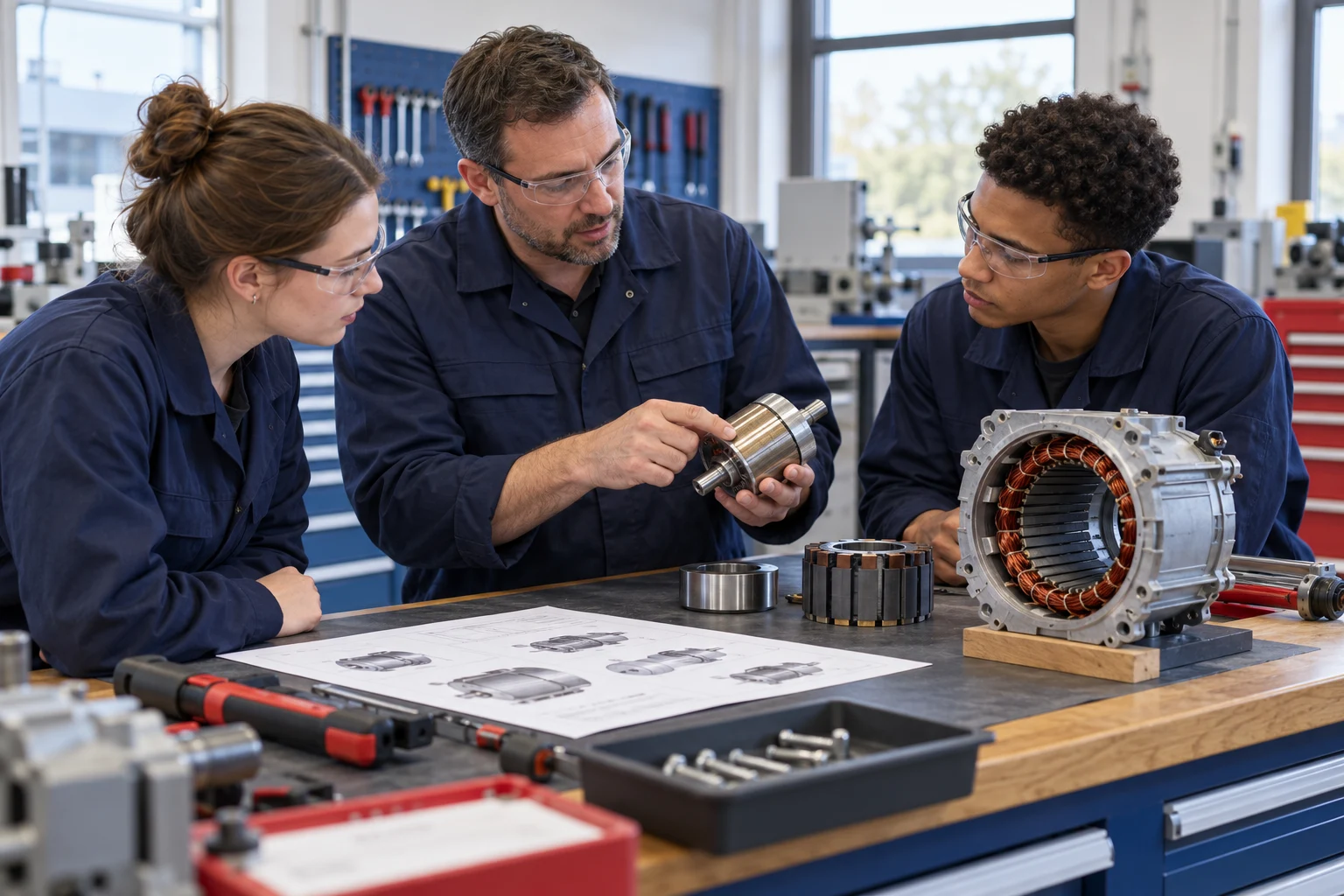
From motor components to measured performance.
An electric drive laboratory should help learners explain what they assemble, justify what they measure and interpret how a motor behaves under controlled conditions.
This training pathway connects permanent-magnet motor construction, supervised assembly, electrical inspection, guided diagnosis and performance analysis. It is designed for vocational automotive programmes, technician training centres and faculty developing an electric drive course.
Students should already understand basic electrical circuits, measurement instruments and workshop procedures. Learners entering from a general mechanical programme may need a foundation module before practical electrical work.
What learners should be able to demonstrate.
Each outcome needs observable evidence. Equipment access alone does not demonstrate that a learner can complete the task independently.
Explain the electric drive system
Identify the motor, resolver, controller and relevant connections, then relate component functions to the configured system diagram.
Complete a controlled assembly task
Follow the approved sequence, inspect components and document the checks required before the next practical activity.
Diagnose with measurement evidence
Select an appropriate instrument, record test conditions and use the permitted measurements to support a fault explanation.
Interpret motor performance
Read speed, torque and performance results from the test platform and explain what the recorded operating conditions allow the data to show.
A six-stage learning route.
Move from understanding and preparation to practical evidence. Open a stage to see the activity, equipment role and expected record.
01System awareness and preparation
Understand the system before practical work.
Practical activity
Use the actual system diagram to identify motor construction, controller connections, feedback signals and instructor-controlled work boundaries. Review instrument selection and the approved procedure before handling equipment.
Teaching equipment: T036; diagrams and optional motor simulation.
Evidence to retain
Annotated component map and a prerequisite check. A learner must explain the intended task before starting.
02Motor disassembly and component inspection
Link construction with assembly decisions.
Practical activity
On the configured T036 station, complete the supervised disassembly and inspection sequence. Identify the rotor, stator, resolver and associated components; record observations using the model-specific checklist.
Teaching equipment: T036; selected fixtures and tools.
Evidence to retain
Inspection sheet with component identification, observed condition and the instructor’s release for reassembly.
03Reassembly and measurement checks
Demonstrate a repeatable procedure.
Practical activity
Follow the approved reassembly process and carry out the configured resistance, insulation or resolver-related checks under instructor supervision. Use limits from the equipment procedure; do not substitute a generic acceptance value.
Teaching equipment: T036; instruments specified for the exercise.
Evidence to retain
Assembly checklist and measurement record including instrument identification, method, conditions and the applicable reference.
04Guided electrical fault diagnosis
Build a conclusion from evidence.
Practical activity
Use an instructor-selected fault supported by the delivered configuration. Read the circuit, identify a test plan, take permitted measurements and explain why the evidence supports a particular diagnosis.
Teaching equipment: T036; configured fault box and controller resources.
Evidence to retain
A diagnostic report separating the symptom, initial hypothesis, observations, conclusion and verification.
05Controlled performance testing
Relate operating conditions to motor response.
Practical activity
Move to the separate T076 performance station. The instructor confirms the permitted test conditions, matched equipment and operating procedure before learners observe or conduct the authorised speed and torque exercise.
Teaching equipment: T076; agreed software and test procedure.
Evidence to retain
Test record with the operating points, units, conditions and measured results. Each station retains its own approved setup.
06Interpretation and practical assessment
Explain the result and its limits.
Practical activity
Compare the permitted operating points and interpret the corresponding performance curves. Combine the assembly record, diagnostic reasoning and performance report into an assessed practical portfolio.
Teaching equipment: T036 records; T076 results; assessment rubric.
Evidence to retain
An individual evidence portfolio and a short oral explanation. A group’s completed exercise is not automatically evidence of each learner’s competence.
The sequence is a teaching progression. It does not imply that the two stations share a motor, power supply, control system or mechanical interface.
Two platforms. Distinct teaching roles.
Select equipment by the task students need to perform. Keep assembly and diagnosis separate from controlled load testing when defining the technical schedule.
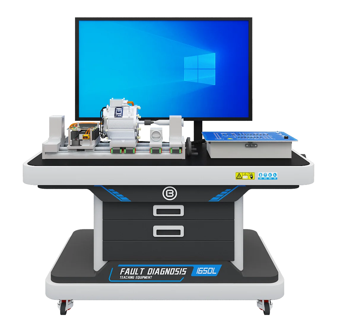
Drive Motor Assembly & Testing Training System
A practical station for permanent-magnet motor assembly, resolver adjustment, mechanical inspection and guided drive-circuit diagnosis.
Teaching roleStages 1–4: component awareness, assembly, measurement and diagnosis.
View Equipment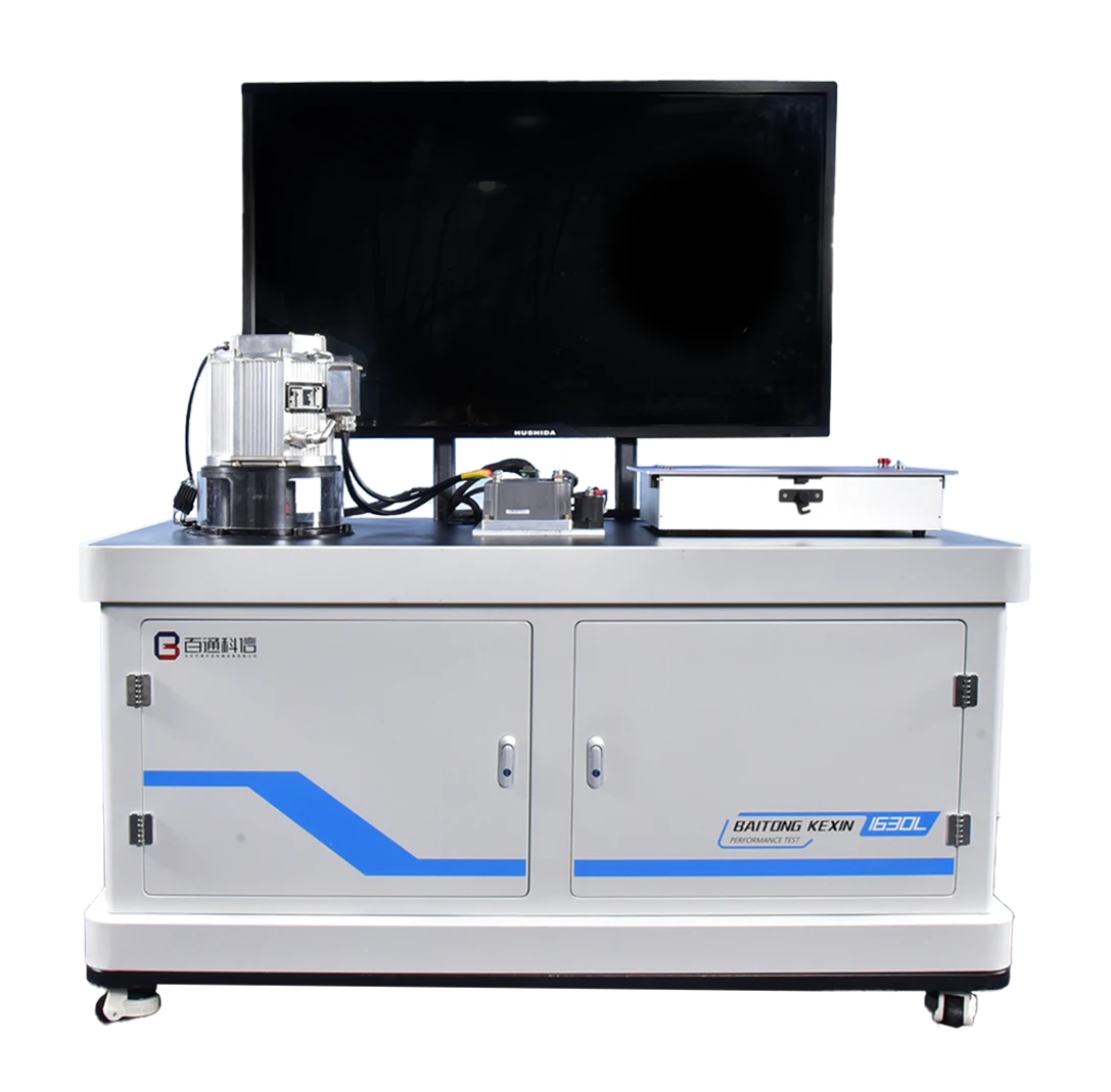
Drive Motor Performance Test & Analysis Platform
A dynamometer teaching station for controlled load tests, speed and torque measurement, and performance-curve analysis.
Teaching roleStages 5–6: measured motor response and interpretation of test results.
View Equipment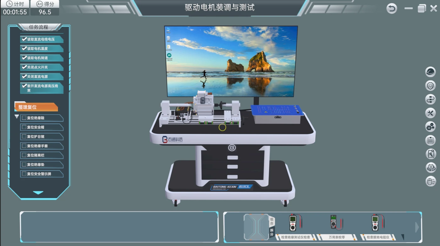
Prepare the procedure in simulation.
Optional electric motor simulation can support assembly sequences and diagnostic reasoning before practical work. Software scope, licenses, language and hardware are confirmed for the project.
Explore the simulation resourceEquipment connected to a usable course pack.
Plan the course resources with your teaching team alongside the equipment. Agree which lesson plans, student materials, instructor guidance and assessment records your programme needs, and include them in the project scope.
Course and lesson plan
Learning outcomes, entry requirements, lesson sequence, practical hours and equipment allocation agreed with the institution.
Student task sheets
Task briefs, component maps, measurement records and diagnostic report formats matched to the delivered station.
Instructor resources
Demonstration guidance, reference answers, fault-setting instructions and observation points for supervised practical work.
Assessment materials
Practical rubrics, individual evidence requirements and feedback forms, with the assessment responsibility defined by the school.
A course-to-equipment map your faculty can review.
| Learning unit | Equipment or resource | Student output |
|---|---|---|
| System construction | T036, system diagrams and optional motor simulation. | Annotated component map explaining the motor, feedback and controller roles. |
| Assembly and inspection | T036 with the specified fixtures, tools and instruments. | Assembly checklist and traceable inspection measurements. |
| Electrical diagnosis | T036 configured circuits, fault box and instructor task sheet. | Diagnostic report linking the observed symptom, test evidence and conclusion. |
| Performance analysis | T076 configured test system, approved exercise and available result output. | Operating-point record, interpretation of results and individual explanation. |
What a practical task can look like.
Explain the response at two permitted operating points.
This sample shows how a T076 lesson can connect equipment operation with interpretation. It contains no measured results or prescribed test settings.
- Prepare the exercise. The instructor confirms the approved procedure, configured motor and test system, permitted operating points and student responsibilities.
- Capture the conditions. Record the station identification, software version, units, operating conditions and the instructor-approved test plan.
- Record the evidence. Enter the observed speed and torque for each permitted point, retaining available output or screenshots with the task record.
- Interpret the response. Explain what changed, which conditions were held or recorded, and what additional evidence would be needed for a broader conclusion.
- Review individually. Each learner explains one observation and one limit of the exercise. The instructor records feedback and any required repeat task.
Assess the work, the evidence and the reasoning.
Agree the rubric with the teachers who will assess the course. Weightings and pass criteria belong to the institution’s approved assessment plan; the table gives a structure to adapt.
| Assessment area | What the assessor observes | Evidence retained |
|---|---|---|
| Preparation | Correct task identification, prerequisites and authorisation for the activity. | Preparation check and task briefing. |
| Assembly and inspection | Following the procedure and documenting required component checks. | Inspection and assembly checklist. |
| Measurement quality | Suitable instrument, documented conditions, correct units and traceable observations. | Completed measurement sheet. |
| Diagnostic reasoning | A conclusion supported by observations and an appropriate verification step. | Diagnostic report and assessor questions. |
| Performance interpretation | An explanation that reflects the recorded conditions and the limits of the test. | Result report and individual explanation. |
Plan for active learners, not just equipment count.
Define how many students can carry out a meaningful task while the instructor supervises practical work. One demonstration station may serve a class presentation, but it does not provide simultaneous hands-on practice for every learner.
| Planning decision | What to confirm |
|---|---|
| Class and rotation | Class size, group size, time per task, individual evidence and the number of supervised sessions available. |
| Room and services | Access, working clearances, guarding, floor suitability, utilities and the actual electrical supply at the destination. |
| Test station installation | T076 specifies a 380 V AC three-phase working supply and a separate 220 V AC dynamometer supply. The project schedule must define the installed requirements. |
| Teaching resources | Display visibility, student recording arrangements, software licenses and access to the required language materials. |
| Phased investment | An assembly-first phase can establish stages 1–4. Add the dedicated performance station when stages 5–6 enter the approved course. |
Make the rotation plan testable.
Prepare a timetable against a specific task before deciding that one station is sufficient. Record the time needed for instructor preparation, each group’s permitted activity, restoration of the equipment and review of the resulting evidence. A learner watching another group is participating in observation, but that record should remain distinguishable from performing an assessed assembly or measurement step.
For an illustrative planning calculation, a class of 24 divided into groups of four creates six group visits to each required station. This calculation describes visits only; it does not establish a safe group size or a lesson duration. The teacher must still define the active roles, permitted operation and supervision arrangement. Where assembly and performance work cannot be supervised simultaneously, stagger those activities and use diagram study or result interpretation between practical visits.
Review the first delivered lesson with the faculty. If the evidence sheet shows that one student performed every practical action while the others recorded results, adjust the role rotation or schedule another observed task. Equipment quantities, lesson time and assessment design should be reviewed together. The useful procurement output is a documented capacity assumption tied to the actual lesson, rather than a universal claim that a station serves a fixed number of students.
Explore laboratory planningHow the pathway becomes a teaching project.
The project connects three deliverables: a defined equipment configuration, matched learning materials and teachers prepared to use them. Scope each layer before production and course development begin.
Define the teaching brief
Review learner entry level, local programme requirements, existing equipment, intended tasks and the institution’s assessment approach.
Deliverable: agreed outcomes and a project requirements brief.Match equipment and site conditions
Select the stations, tools, instruments and software; identify room services, local installation responsibilities and any phased scope.
Deliverable: model-specific equipment schedule and site preparation list.Develop the course resources
Connect each agreed outcome to a lesson, student task and assessment record. Review terminology, language, faculty contributions and resource rights.
Deliverable: agreed course map and the specified teaching resource package.Commission and prepare teachers
Follow the agreed installation scope, demonstrate the delivered tasks and give teachers practical familiarisation with equipment and resources.
Deliverable: commissioning records and teacher training records.Accept the project and hand over support
Check the delivered configuration, documents, agreed functions and resource access. Record unresolved items and confirm the support contact and responsibilities.
Deliverable: acceptance record, resource inventory and support handover.
Equipment and teaching support in practice.
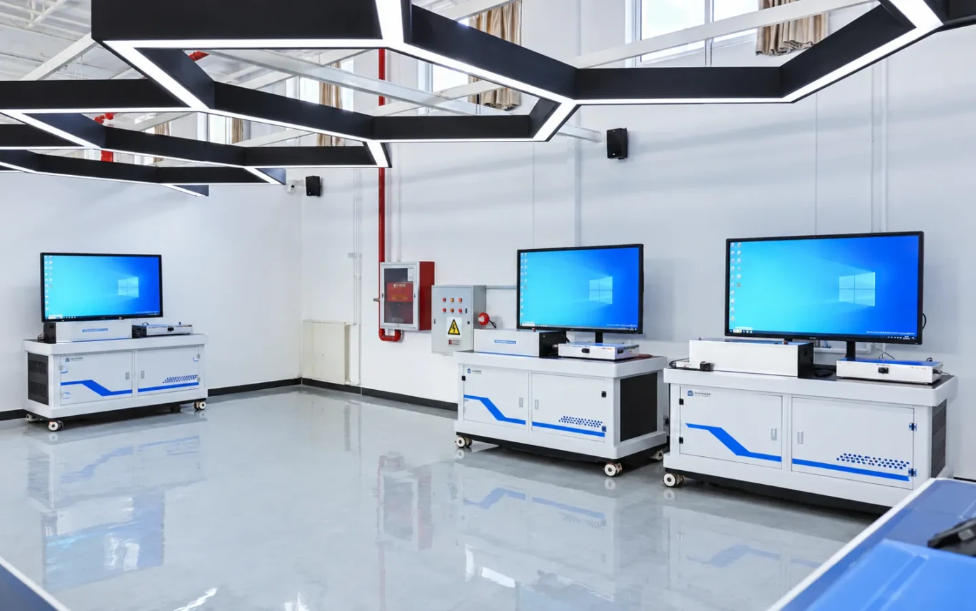
Beijing Commercial School NEV Practice Center
The project connects system awareness, whole-vehicle practice, battery performance and drive-motor performance in four teaching zones.
Task sheets, micro-lessons, operation videos and instructor orientation were matched to the delivered stations.
For your institution, agree the selected stations, matched teaching materials and instructor preparation as one project package.
Explore the projectAdapt the pathway to the destination programme.
Keep the learning logic consistent while checking the requirements that change between institutions and countries.
Curriculum and assessment
Map the proposed outcomes to the institution’s current syllabus and cited local competency requirements. Identify gaps before claiming alignment.
Language and terminology
Confirm separately the teaching language, document translations, interface language, subtitles and teacher training arrangements.
Utilities and configuration
Review local supply conditions, installation obligations and equipment documentation. Component ratings do not replace destination-specific checks.
Institutional responsibilities
Agree who approves the course, assesses students, maintains the equipment and provides local support. Qualification recognition requires its own evidence.
Questions Before You Configure the Pathway.
Does every institution need both platforms?
No. An assembly and diagnostic course may begin with the T036 scope. The T076 addresses the separate performance-testing outcomes. Choose the equipment after confirming the course, practical tasks and existing laboratory resources.
Can the same motor be moved from T036 to T076?
That compatibility is not assumed. The pathway links teaching objectives, not a verified interchangeable motor or shared interface. Any transfer or connection requires explicit confirmation for the selected configurations.
Are course materials included with every equipment order?
Agree the curriculum, task sheets, media, software and assessment documents as itemised deliverables. Course co-development is available; confirm the custom course pack separately from the hardware quotation.
Does the pathway provide a recognised local qualification?
It is a reference teaching framework. The institution and relevant authorities determine qualification approval and assessment requirements. Any mapping to a named standard needs a documented review of that standard and its current version.
How many students can one station serve?
There is no universal ratio. Determine the number of active learners, the task duration, supervision needs and individual evidence requirements. Use those decisions to plan group rotation and the number of stations.
Can existing equipment be used in the pathway?
Yes, the project brief can start with an inventory of your current stations, tools and software. Review their supported tasks and documentation before deciding which outcomes need new equipment or resources.
Explore Further
Equipment, Services & Project Details.
Explore product specifications, teaching support and project examples to help plan the equipment and course resources for your institution.