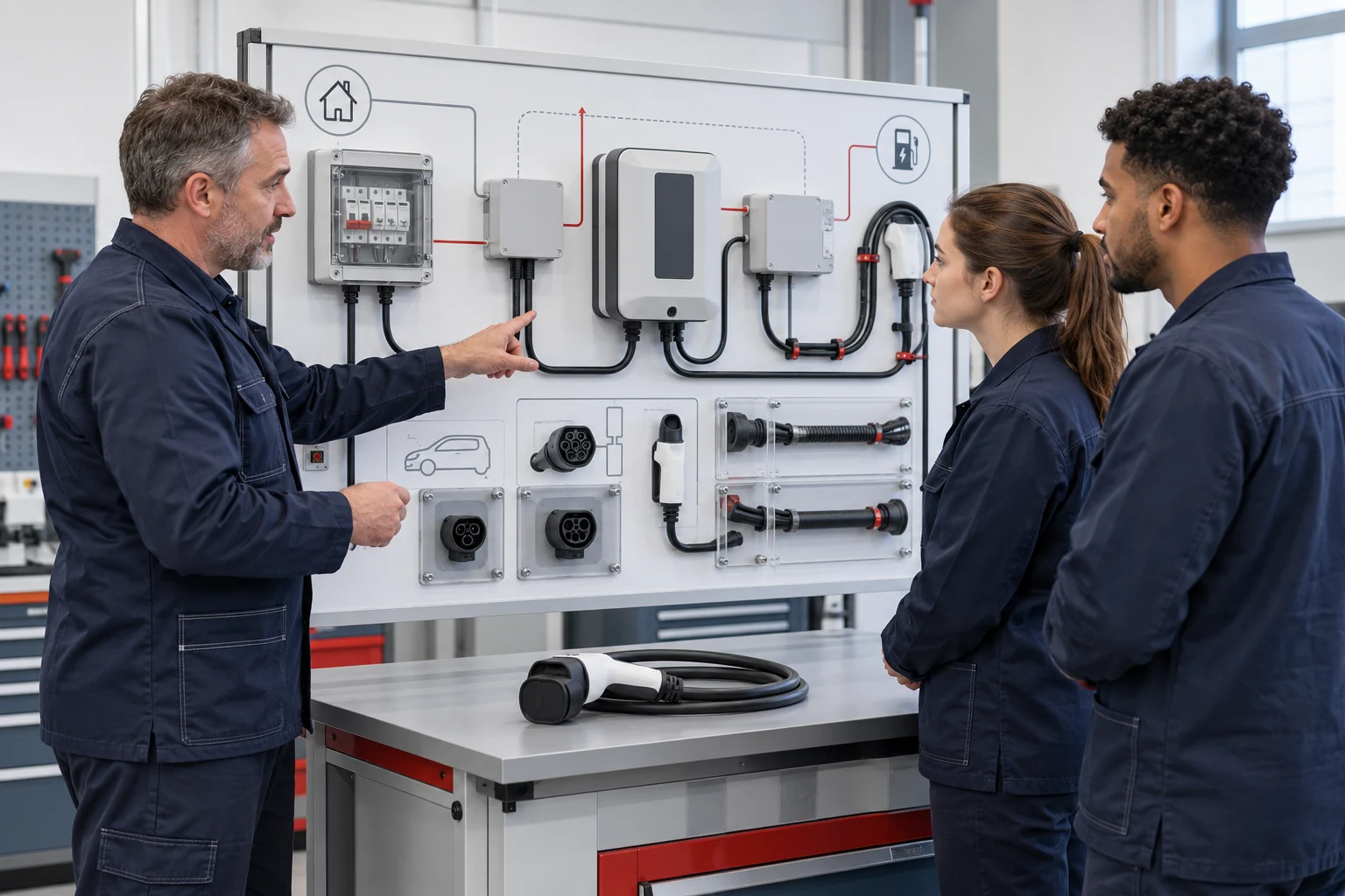

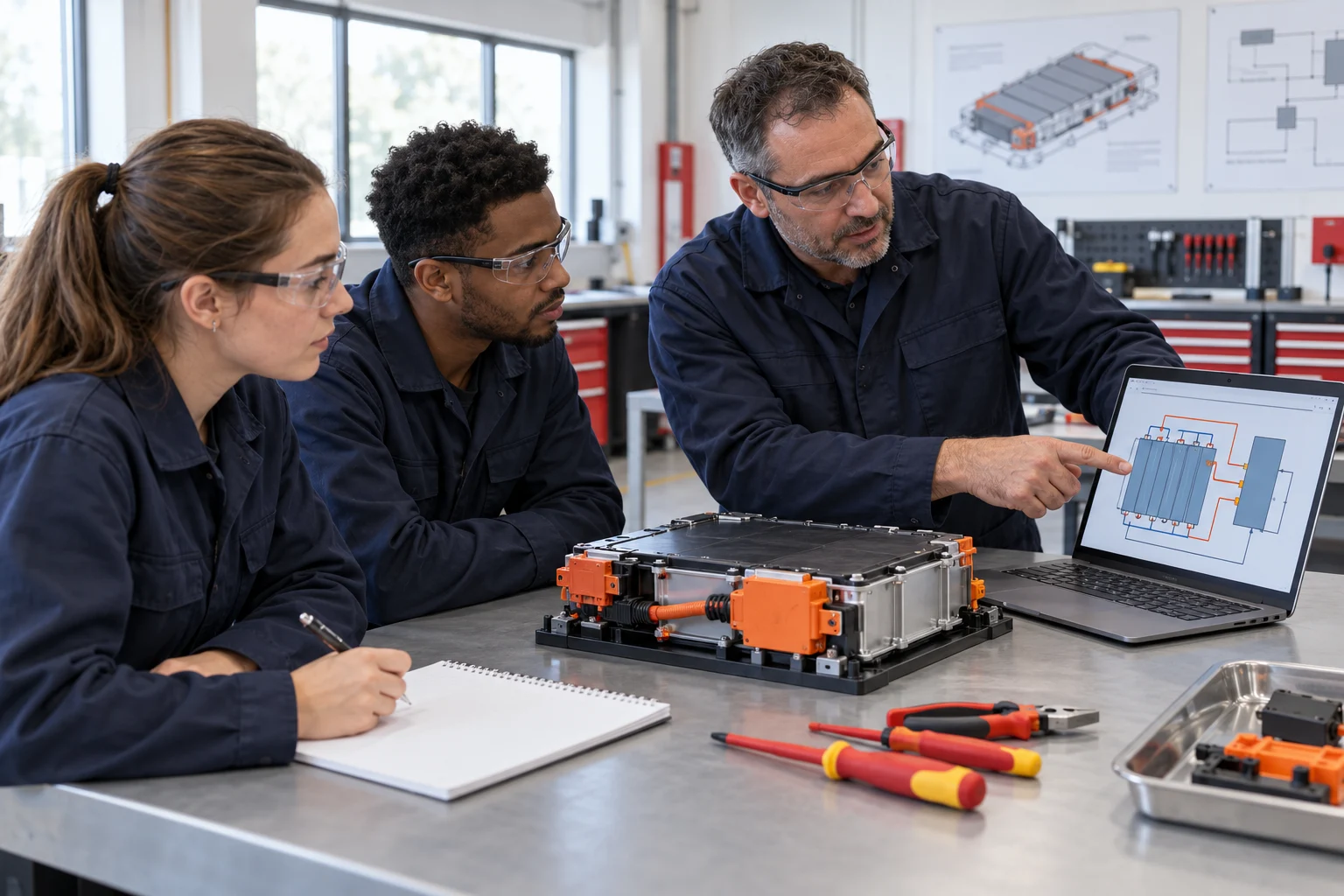
A battery course built around traceable decisions.
Battery assembly training becomes more useful when learners can explain why a component was accepted, how an assembly was checked and what a BMS reading actually represents.
This training pathway connects cell inspection, module and pack assembly, commissioning records, physical measurement and BMS interpretation. It is intended for vocational automotive programmes, technical institutes and technician training centres that need an equipment-based battery course rather than a demonstration of disconnected components.
The principal physical resource is the BT-NEV2-T028 EV Battery Assembly & BMS Training System. Its documented scope includes cell voltage and internal-resistance measurement, assembly, component inspection, BMS information, selected circuit faults, air-tightness work and charge-discharge exercises within the confirmed configuration. A separate performance platform can extend the course into more structured cycling, capacity and DC internal-resistance analysis.
The pathway begins with basic circuit knowledge and the ability to use the selected instruments under supervision. Faculty should identify any missing electrical foundations before assigning pack-level practical tasks. Adapt the learning sequence and assessment framework to your programme’s prerequisites, hours and learning outcomes.
Four capabilities to develop and assess.
Make a defensible sorting decision
Identify the cells, record comparable voltage and internal-resistance observations, apply the supplied criteria and explain the reason for a grouping or referral.
Document the assembly process
Identify the component and harness functions, follow the approved sequence and retain the checks required before commissioning.
Interpret monitored data
Relate physical observations to the BMS display while distinguishing a measured quantity, a reported state and an estimated value such as state of charge.
Diagnose a supported circuit condition
Use the configured circuit information and permitted measurements to explain an instructor-selected fault, then document the verification required for the task.
The outcome is a learner who can connect evidence with a decision. A completed worksheet, an attractive software screen or an assembled pack is useful only when the learner can explain how the result was obtained.
Six stages from cell records to diagnostic evidence.
Use the stages as a sequence, with an instructor review between tasks that depend on earlier work. The actual cell acceptance criteria, assembly checks and operating conditions come from the delivered configuration and approved procedure.
01Identify the battery system and evidence sources
Build a common vocabulary before practical work.
Learning activity
Identify the LFP cells, module, contactors, precharge components, current and temperature sensing, service disconnect, charger and BMS on the configured T028 system. Trace their functions using the actual diagram. Distinguish a physical instrument reading from a value communicated to the software.
Teaching resource: T028, a component map and the selected procedure; optional BT-DCVR can rehearse the identification sequence.
Evidence to retain
An annotated system map identifying the source of each observation. Ask the learner which information could change if the cell connection, sensor input or communication path changed.
02Measure cells and explain a sorting decision
Record comparable observations, not just a final group.
Learning activity
Identify each assigned cell and follow the supervised measurement method for voltage and internal resistance. Record the instrument, units and relevant conditions. Compare the results with the supplied selection criteria and explain whether the observations support the proposed grouping or require review.
Teaching resource: T028 cells and the specified battery-resistance and electrical instruments.
Evidence to retain
A cell register with original readings, the acceptance reference and the sorting explanation. One similar voltage reading is not a sufficient record of complete cell consistency.
03Assemble and inspect the documented configuration
Connect component identity with the assembly sequence.
Learning activity
Complete the permitted module or pack task, identify the documented high- and low-voltage harnesses, and inspect the specified connectors and components. Include the configuration’s required marking and check records. Thermal-management interfaces and air-tightness work are included only where the actual exercise provides the necessary equipment and procedure.
Teaching resource: T028, selected fixtures, tools and a model-specific checklist.
Evidence to retain
An assembly record that distinguishes work completed, checks observed and items referred to the instructor. Preserve the release decision before proceeding to the next activity.
04Compare measurements with BMS information
Understand why two values may describe different things.
Learning activity
Review permitted cell or pack measurements alongside the relevant BMS channel. Record which quantity, location and time each entry represents. Relate temperature, current, relay status and charger information to the selected exercise. Treat SOC as a reported estimate whose meaning depends on the configured BMS and conditions.
Teaching resource: T028 instruments, BMS software and the documented CAN connection.
Evidence to retain
A paired observation sheet with units, source, conditions and an explanation. A discrepancy starts an investigation into method, timing or channel identification; it does not by itself prove that a component is defective.
05Investigate an instructor-selected circuit fault
Use a hypothesis, a test plan and a supported conclusion.
Learning activity
Work with a fault supported by the delivered manual fault-setting arrangement, such as a selected sensing, contactor-control or precharge-related circuit condition. Read the actual circuit and define the permitted observations before measuring. Compare the findings with the initial explanation and document the verification specified by the instructor.
Teaching resource: T028 fault box, circuit information and suitable instruments.
Evidence to retain
A diagnostic report separating symptom, hypothesis, observed evidence, conclusion and verification. Reward a justified revision of the hypothesis rather than an unsupported correct guess.
06Commission, review and assess individually
Combine the records into a practical portfolio.
Learning activity
Review the required assembly and commissioning records, including any authorised charge-discharge exercise in the selected T028 configuration. Compare the observed operation with the task criteria. Each learner explains one inspection decision, one BMS interpretation and one limit of the available evidence.
Teaching resource: T028 practical records and an institution-approved assessment rubric.
Evidence to retain
An individual portfolio and assessor feedback. Where performance analysis is added, retain separate records for the T068 test conditions rather than implying that assembly completion establishes battery life or durability.
Select equipment for the question being taught.
The T028 supports the main assembly, measurement and BMS pathway. Simulation is useful preparation; the T068 is an optional extension when the curriculum requires dedicated performance experiments. Their roles should be itemised separately in the configuration schedule.
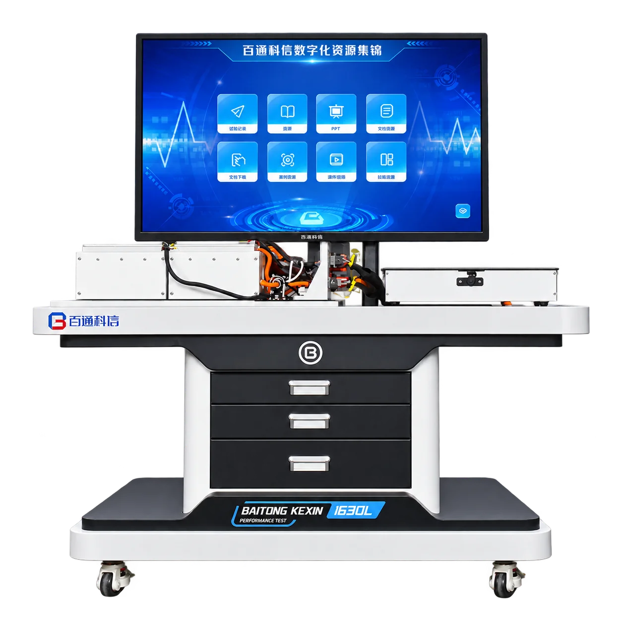
EV Battery Assembly & BMS Training System
An LFP training station combining battery assembly, specified instruments, manual fault setting and BMS monitoring.
Teaching roleCore physical resource for cell inspection, module and pack tasks, BMS interpretation and guided circuit diagnosis.
View Equipment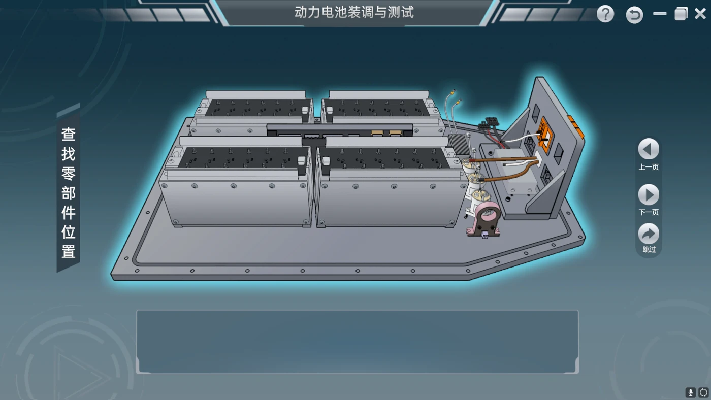
Battery Assembly and BMS Simulation Software
Client/server desktop simulation with demonstration, teaching and assessment modes for configured battery and BMS tasks.
Teaching roleOptional preparation and virtual evidence before separate supervised physical tasks; language and license scope are confirmed.
View Equipment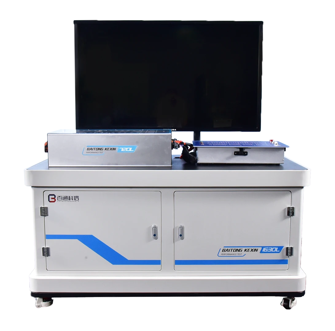
EV Battery Performance Test & Analysis Platform
A dedicated teaching platform for programmable charge-discharge testing, capacity work and DC internal-resistance analysis.
Teaching roleOptional extension when performance experiments require a separate controlled test and analysis scope.
View EquipmentSubject matter can be coordinated across the products. Shared packs, automatic data transfer and physical interfaces require configuration-specific confirmation.
Turn the equipment list into a course map.
Each teaching unit should identify the task students perform and the evidence a teacher can review. This prevents the course from becoming a sequence of product demonstrations with no individual assessment.
| Learning unit | Equipment and resource | Student evidence |
|---|---|---|
| Cell inspection | T028, specified instruments and selection criteria. | Identified readings and a justified sorting decision. |
| Assembly and commissioning | T028, component diagram and approved work sequence. | Component checks, assembly record and instructor release. |
| BMS interpretation | T028 monitoring software and paired measurement sheet. | Physical and reported observations with conditions and explanation. |
| Circuit diagnosis | T028 configured fault arrangement and task-specific diagram. | Hypothesis, permitted measurements and verification. |
| Optional performance extension | T068, agreed test programme and analysis resources. | Conditions, test output and a conclusion within the experiment’s limits. |
Teach the meaning of the data, not only the display.
A useful BMS lesson asks learners to identify the quantity, its source and the conditions under which it was recorded. Pack voltage, an individual cell channel and a reported SOC value answer different questions. A comparison becomes meaningful only after the learner confirms that the records refer to the intended point and relevant operating state.
For example, a cell register taken during an earlier inspection is not automatically a simultaneous reference for a later software screen. The task sheet should therefore retain time or sequence information and describe whether a value came from the instrument, the BMS or the instructor’s reference. Students can then discuss possible causes of disagreement without immediately replacing a component.
Instrument resolution and BMS sampling characteristics also have different meanings. The T028 BMS has a specified cell-voltage sampling accuracy of ≤5 mV, but this is not a universal tolerance for every comparison exercise. Use the specified measurement method and documented equipment information when defining the task criteria.
A sample task: reconcile a cell record and a BMS channel.
Explain the observation before declaring a fault.
This illustrative task combines measurement quality with diagnostic reasoning. The instructor selects the permitted comparison and supplies the configuration-specific method; the template contains no fabricated readings or fixed acceptance limits.
- Identify the evidence. Record the assigned cell or channel, instrument identification, relevant BMS screen and the approved procedure reference.
- Record comparable conditions. State the operating condition and the observation sequence. Identify any difference between the physical point measured and the reported channel.
- Document the result. Enter the actual reading and units, then retain the available screen or record reference.
- Explain agreement or disagreement. Consider identification, timing, method and the applicable reference before proposing a component fault.
- Review the conclusion. State the further evidence required and obtain instructor feedback on the reasoning.
Assessment focus: traceable records, correct interpretation and a justified next step rather than an unsupported pass/fail label.
Open Printable Task SheetAssess the learner’s decisions as well as the finished work.
Use direct observation and short individual questions alongside the portfolio. For a group exercise, assign changing roles such as recorder, diagram reader and measurement planner, then confirm what each learner actually demonstrated. The institution determines weighting and pass criteria.
| Assessment area | Observable performance | Record retained |
|---|---|---|
| Cell decisions | Applies the supplied selection criteria to identified readings. | Cell register and reasoned decision. |
| Assembly discipline | Follows the approved sequence and records required checks. | Checklist and instructor observations. |
| Measurement quality | Chooses the specified instrument and records units and conditions. | Measurement sheet and method reference. |
| BMS interpretation | Distinguishes physical values, reported states and estimates. | Paired observation and explanation. |
| Diagnostic reasoning | Supports the conclusion and identifies any unresolved question. | Diagnostic report and individual review. |
Specify the teaching package beside the hardware.
Faculty course plan
Entry requirements, learning sequence, practical allocation and the criteria used at each review point.
Student records
Component maps, cell registers, assembly checks, paired BMS observations and diagnostic report templates.
Instructor references
Model-specific task guidance, supported faults, demonstration notes and the evidence expected from an acceptable explanation.
Digital preparation
Selected BT-DCVR modules, account arrangements, media language and the method for reviewing virtual task results.
Curriculum co-development can connect these resources with the institution’s own programme. Confirm the material list and resource rights in the project scope. The simulation uses client/server desktop deployment and Mandarin narration; translation and any alternative deployment need separate agreement.
Plan a workshop rhythm that preserves individual evidence.
Allocate time for identification, practical work and explanation. A class that rotates rapidly past one station may observe the demonstration but produce little individual evidence. Decide which tasks need direct manipulation and which can be prepared at a separate desk or software workstation.
A practical rotation can combine a diagram-and-planning activity, the supervised T028 task and an evidence-review activity. Set the duration using the actual exercise and teacher observation requirements. Retain one named record for each learner even when a group shares a station; a group submission should not hide a learner who has not interpreted the result.
Before fixing quantities, review battery handling and storage arrangements, working access, the selected electrical services, tool control and required supervision. If charge-discharge tasks or the optional T068 are included, define their installation and test requirements separately. For the T068, use the current ≤4 kW and ±30 A configuration when planning the equipment schedule.
Deliver a defined course capability in five steps.
Confirm the programme and existing resources
Review learner level, intended occupational tasks, current equipment and faculty assessment requirements. Identify which stages are needed first.
Output: agreed outcomes and a course-to-equipment scope.Freeze the physical and software configuration
Specify the training battery, instruments, permitted tasks, selected faults, licenses, languages, site services and accessories.
Output: model-specific schedule and resource inventory.Prepare and review the teaching records
Develop the student templates and instructor references, checking that each exercise matches the ordered configuration and institutional criteria.
Output: reviewed task pack and assessment structure.Commission and familiarise the teachers
Demonstrate the agreed tasks, practise recording evidence and review how the selected BMS and fault resources support explanation.
Output: commissioning and teacher familiarisation records.Accept the agreed scope and hand over support
Check hardware, resource access, documents and outstanding items against the agreed schedule. Confirm support responsibilities and document revisions.
Output: acceptance record and support handover.
Adapt the course to the institution and destination.
Start local adaptation with the current syllabus and the real battery tasks graduates are expected to perform. A programme focused on inspection may need a different depth of pack assembly or cycling analysis from a production-oriented course. Cite the relevant local competency document and its version when claiming a match.
Review electrical supply, installation responsibilities, teaching terminology and access to translated instructions. Confirm software interface language, narration, worksheets and teacher training language separately. Students should not need to translate a critical task instruction while attempting the exercise.
For institutions extending the learning route, the AC charging diagnostics pathway examines charging-control tasks, while electric drive training develops assembly-to-performance reasoning in a different system. The virtual-to-practical pathway explains how to combine preparation with observed physical competence.
Extend into performance analysis only when the question requires it.
The T028 includes charge-discharge exercises within its confirmed configuration. Use those activities to connect assembly and BMS observations with operation. When the teaching question requires programmable cycling, capacity measurement or DCIR analysis, review the separate T068 performance platform and define an appropriate experiment.
Specify the test object, conditions, sequence and result format before comparing data. A short teaching exercise does not establish long-term service life. Physical compatibility between a battery and another station depends on the selected chemistry, voltage, current, communication and handling requirements.
For the combined laboratory, lab planning can coordinate equipment and supervision, while teacher training can prepare staff to teach and assess the agreed tasks. Explore battery service training to plan related practical tasks and laboratory needs.
Questions Before You Configure the Pathway.
Can T028 support charge-discharge exercises?
Yes. T028 supports charge-discharge work within the confirmed configuration, alongside assembly, measurement and BMS diagnosis. Dedicated programmable cycling, capacity and DCIR analysis are the role of the separate T068 performance platform.
Does a BMS SOC reading prove the battery’s measured capacity?
No. SOC is a reported estimate that must be understood in the configured BMS context. Capacity measurement requires a defined performance test and its conditions. The lesson should distinguish these quantities rather than treating a display value as a complete performance result.
Can simulation replace the practical battery assessment?
BT-DCVR can rehearse assembly and selected diagnosis tasks and retain virtual records. Its scores describe work inside the software. Instrument handling, physical assembly and practical measurement need observation on the appropriate equipment.
Is one set of acceptance limits valid for every training battery?
No. Cell selection, assembly checks and operating criteria must come from the actual configuration and approved procedure. The sample task sheets provide a recording structure; the institution and project team complete the applicable criteria.
Are translated resources included automatically?
Language is a scope item. Specify student worksheets, instructor guidance, software interface, narration, subtitles and teacher training separately. The simulation currently provides Mandarin narration; other language provision needs confirmation.
What should an institution provide before equipment is configured?
Provide the learner level, course outcomes, class size, existing laboratory inventory, intended battery tasks, destination utilities and resource language. These determine the station roles, practical rotation and course development scope.
Explore Further
Equipment, Services & Project Details.
Explore product specifications, teaching support and project examples to help plan the equipment and course resources for your institution.